I am having a bit of confusion around how to interpret a feature that has both position and perpendicularity tolerances attached to it. I get that the position control will, by itself, restrict the orientation and my understanding was that an additional orientation control was only added if tighter control of the orientation was necessary for functionality.
The reason this is messing me up is because I was under the impression that cylindrical tolerance zones and VC's for position tolerances were located by basic dimensions (i.e. placed at the true position of the feature). Since orientation tolerances don't fix the position, I assumed their tolerance zones and VC's would be floating and that the UAME axis or feature surface just needed to fit in the appropriately sized cylindrical tolerance zone (or not intersect the VC), but that the cylindrical tolerance zone and VC could "slide" around to find a successful configuration (in the absence of positional tolerance).
This lead me to an interesting dilemma on how to apply the bonus tolerance when the UAME deviates from MMC.
Here is the example that got me thinking:
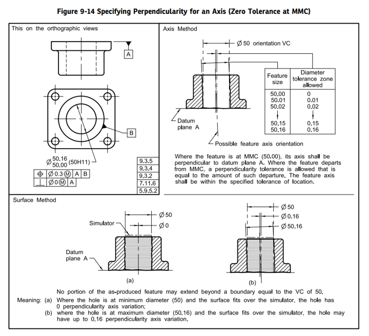
They seem to be analyzing only the orientation(perpendicularity) tolerance, which makes sense as the example is in the orientation tolerance section. They use a 50mm "orientation VC" this suggests to me that the orientation control is to be considered independently of the position tolerance. I can't tell from the pictures if the positions of the "orientation VC" and tolerance zones are fixed at the true location w.r.t. datum B or if they are "floating". Am I wrong? Are the positional VC and orientation VC both fixed at the true position?
I get the advantage of shifting the perpendicularity tolerance to the size tolerance and then allowing the bonus tolerance as the UAME departs from MMC to control the perpendicularity (and position), but I don't understand the correct approach to analyzing the combined effect of both the position and the perpendicularity tolerances.
Logically, I would think these two controls would be verified separately (along with the size tolerance). The positional VC (surface method) and tolerance zone cylinder (axis method) would be fixed at the true position, while the perpendicularity VC and tolerance zone cylinder would be "floating". At MMC, it is pretty straightforward as the tolerance zone diameter would be zero for the perpendicularity control and 0.3 for the positional control.
The problem is that as the UAME departs from MMC. Bonus tolerance is available, but how would it be "distributed" between the two controls? For instance, if the UAME had a diameter of 50.15, then there would be 0.15 bonus tolerance available. Would this be shared between the position and orientation controls, or, would each analysis be provided with the extra 0.15? The former makes more sense to me from a big picture assembly interference avoidance standpoint.
I feel like I am getting pretty deep in the weeds on this, but I really want to understand the appropriate methodology.
Can one of you sage GD&T folks help me understand the correct way to analyze this problem?
The reason this is messing me up is because I was under the impression that cylindrical tolerance zones and VC's for position tolerances were located by basic dimensions (i.e. placed at the true position of the feature). Since orientation tolerances don't fix the position, I assumed their tolerance zones and VC's would be floating and that the UAME axis or feature surface just needed to fit in the appropriately sized cylindrical tolerance zone (or not intersect the VC), but that the cylindrical tolerance zone and VC could "slide" around to find a successful configuration (in the absence of positional tolerance).
This lead me to an interesting dilemma on how to apply the bonus tolerance when the UAME deviates from MMC.
Here is the example that got me thinking:
They seem to be analyzing only the orientation(perpendicularity) tolerance, which makes sense as the example is in the orientation tolerance section. They use a 50mm "orientation VC" this suggests to me that the orientation control is to be considered independently of the position tolerance. I can't tell from the pictures if the positions of the "orientation VC" and tolerance zones are fixed at the true location w.r.t. datum B or if they are "floating". Am I wrong? Are the positional VC and orientation VC both fixed at the true position?
I get the advantage of shifting the perpendicularity tolerance to the size tolerance and then allowing the bonus tolerance as the UAME departs from MMC to control the perpendicularity (and position), but I don't understand the correct approach to analyzing the combined effect of both the position and the perpendicularity tolerances.
Logically, I would think these two controls would be verified separately (along with the size tolerance). The positional VC (surface method) and tolerance zone cylinder (axis method) would be fixed at the true position, while the perpendicularity VC and tolerance zone cylinder would be "floating". At MMC, it is pretty straightforward as the tolerance zone diameter would be zero for the perpendicularity control and 0.3 for the positional control.
The problem is that as the UAME departs from MMC. Bonus tolerance is available, but how would it be "distributed" between the two controls? For instance, if the UAME had a diameter of 50.15, then there would be 0.15 bonus tolerance available. Would this be shared between the position and orientation controls, or, would each analysis be provided with the extra 0.15? The former makes more sense to me from a big picture assembly interference avoidance standpoint.
I feel like I am getting pretty deep in the weeds on this, but I really want to understand the appropriate methodology.
Can one of you sage GD&T folks help me understand the correct way to analyze this problem?