Eng-Tips is the largest engineering community on the Internet

Intelligent Work Forums for Engineering Professionals

  • Congratulations waross on being selected by the Eng-Tips community for having the most helpful posts in the forums last week. Way to Go!

Multiple Holes Normal to Surface Macro 2

Status
Not open for further replies.

jzecha

Aerospace
Jan 20, 2016
235
US
I am looking for a Macro that will create 100+ of the same hole normal to a complex part surface.

I start with hole axises, but I can intersect those with the part surface to create intersection points.
I have searched this forum and found references to PKT license, which I do not have.

I have been running CREO most of this year and I have gotten used to its easy ability to pattern 3D holes.
 
Replies continue below

Recommended for you

Hi.
Can you provide a sample part?
How do you want those surfaces to be sekected/auto-detected by a macro?
 
Give me some time and I can create a dummy part.

Ideally, I select the Geoset with all the Vectors for the holes and then select one surface that all the holes need to be in.
But I want the holes to be Solid Modeled, the surface is just what I split the part with.
The Macro, would cycle through each Vector in the Geoset and reuse the initially selected surface and create the same hole for every vector.

I can create a Geoset with Intersection points instead of the Vectors if that would be easier.
 
What do you mean by "solid modeled" in terms of CATIA commands?
No need to provide intersections.
 
I just mean I need the holes to be in my part and not in the surface.
 
So you want to build Hole features from Part Design, right? What body should be used as an input (PartBody?)? What about hole parameters?
 
I am a little confused as to what you are asking, so I will spell it out to the best of my abilities.

I have a Solid Part that I split with a Joined surface.
I have that Joined Surface as the first feature in a GeoSet labeled "Vectors"
Also, in the GeoSet I have the 100+ Vectors.

I would like to create holes in my Solid part with the Vectors I have.
The part just has the standard "PartBody" name and only has one part body.

As for Hole Parameters, Id prefer a pop up box to ask for Parameters, but If specified beforehand, I could always go in and change it for future uses.

the hole parameters are .375" Diameter x .5" Deep with the standard 120 Degree taper tip at the bottom.

Hopefully this all makes sense, and I really appreciate the help.
I know I have seen something like this out there, just havent had any luck this last week finding it.


jzecha...
here are my premises:
I have a set with points called HoleCenterPoints, located directly under part.
I have an empty body called Holes (holes will end up here)
I have an empty set called Hole_References (line normal to surface and plane normal to curve will be added here for each HoleCenterPoint-point).
My surface is a dead one, i.e. a parameter... called InputSurface (I tested the script on a sphere)
Parameters of the holes are metric, you will need to change it according to your needs.
Sub CATMain()

Dim partDocument1 As PartDocument
Set partDocument1 = CATIA.ActiveDocument

Dim Sel As Selection
Set Sel = partDocument1.Selection

Dim part1 As Part
Set part1 = partDocument1.Part

Dim hybridBodies1 As hybridBodies
Set hybridBodies1 = part1.hybridBodies

Dim hybridBody1 As HybridBody
Set hybridBody1 = hybridBodies1.item("Hole_References")

part1.InWorkObject = hybridBody1

Dim hybridShapeFactory1 As HybridShapeFactory
Set hybridShapeFactory1 = part1.HybridShapeFactory

Dim parameters1 As Parameters
Set parameters1 = part1.Parameters

Dim hybridShapeSurfaceExplicit1 As HybridShapeSurfaceExplicit
Set hybridShapeSurfaceExplicit1 = parameters1.item("InputSurface")

Dim hybridBody2 As HybridBody
Set hybridBody2 = hybridBodies1.item("HoleCenterPoints")

Dim myHybridShape As HybridShape

Dim coord(2)

Dim bodies1 As Bodies
Set bodies1 = part1.Bodies

Dim body1 As Body
Set body1 = bodies1.item("Holes")

For Each myHybridShape In hybridBody2.HybridShapes

myHybridShape.GetCoordinates coord

Dim hybridShapeLineNormal1 As HybridShapeLineNormal
Set hybridShapeLineNormal1 = hybridShapeFactory1.AddNewLineNormal(hybridShapeSurfaceExplicit1, myHybridShape, 0, 20, False)

Dim hybridShapePlaneNormal1 As HybridShapePlaneNormal
Set hybridShapePlaneNormal1 = hybridShapeFactory1.AddNewPlaneNormal(hybridShapeLineNormal1, myHybridShape)

hybridBody1.AppendHybridShape hybridShapePlaneNormal1

part1.InWorkObject = hybridShapePlaneNormal1
part1.UpdateObject hybridShapePlaneNormal1

part1.InWorkObject = body1

Dim shapeFactory1 As ShapeFactory
Set shapeFactory1 = part1.ShapeFactory

Dim hole1 As Hole
Set hole1 = shapeFactory1.AddNewHoleFromPoint(coord(0), coord(1), coord(2), hybridShapePlaneNormal1, 10)

hole1.Type = catSimpleHole
hole1.AnchorMode = catExtremPointHoleAnchor
hole1.BottomType = catVHoleBottom

Dim limit1 As Limit
Set limit1 = hole1.BottomLimit
limit1.LimitMode = catOffsetLimit

Dim length1 As Length
Set length1 = hole1.Diameter
length1.Value = 10

Dim angle1 As Angle
Set angle1 = hole1.BottomAngle
angle1.Value = 120

hole1.SetDirection hybridShapeLineNormal1
hole1.ThreadingMode = catSmoothHoleThreading
hole1.ThreadSide = catRightThreadSide
part1.UpdateObject hole1

Sel.Clear
Sel.Add hybridShapePlaneNormal1
Sel.Add hybridShapeLineNormal1
Set visPropertySet1 = Sel.VisProperties
visPropertySet1.SetShow 1
Next

End Sub

regards,
LWolf
 
This is awesome!
Thanks for the help LWolf.

Only issue I am running into is all of the holes had to be flipped the other direction.
Any Idea how to change the direction a hole goes in within the Macro?

 
hi Jzecha, try changing the normal in
Set hybridShapeLineNormal1 = hybridShapeFactory1.AddNewLineNormal(hybridShapeSurfaceExplicit1, myHybridShape, 0, 20, False)
from False to True


regards,
LWolf
 
That didn't work, I did figure out a work around though, which slows the Macro down a little bit.

I added "hole1.Reverse" right after "part1.UpdateObject hole1"


sorry jzecha, didn't try my suggestion myself, I just assumed the line orientation would flip. my mistake.
do this instead: (I am creating a line based on the endpoints of the normal line. if the direction is opposite, just switch places of the two point references in line command:
Set hybridShapeLinePtPt1 = hybridShapeFactory1.AddNewLinePtPt(hybridShapePointOnCurve2, hybridShapePointOnCurve1)

Sub CATMain()

Dim partDocument1 As PartDocument
Set partDocument1 = CATIA.ActiveDocument

Dim Sel As Selection
Set Sel = partDocument1.Selection

Dim part1 As Part
Set part1 = partDocument1.Part

Dim hybridBodies1 As hybridBodies
Set hybridBodies1 = part1.hybridBodies

Dim hybridBody1 As HybridBody
Set hybridBody1 = hybridBodies1.item("Hole_References")

part1.InWorkObject = hybridBody1

Dim hybridShapeFactory1 As HybridShapeFactory
Set hybridShapeFactory1 = part1.HybridShapeFactory

Dim parameters1 As Parameters
Set parameters1 = part1.Parameters

Dim hybridShapeSurfaceExplicit1 As HybridShapeSurfaceExplicit
Set hybridShapeSurfaceExplicit1 = parameters1.item("InputSurface")

Dim hybridBody2 As HybridBody
Set hybridBody2 = hybridBodies1.item("HoleCenterPoints")

Dim myHybridShape As HybridShape

Dim coord(2)

For Each myHybridShape In hybridBody2.HybridShapes

myHybridShape.GetCoordinates coord

Dim hybridShapeLineNormal1 As HybridShapeLineNormal
Set hybridShapeLineNormal1 = hybridShapeFactory1.AddNewLineNormal(hybridShapeSurfaceExplicit1, myHybridShape, 0, 20, False)


Dim hybridShapePointOnCurve1 As HybridShapePointOnCurve
Set hybridShapePointOnCurve1 = hybridShapeFactory1.AddNewPointOnCurveFromPercent(hybridShapeLineNormal1, 0#, False)

Dim hybridShapePointOnCurve2 As HybridShapePointOnCurve
Set hybridShapePointOnCurve2 = hybridShapeFactory1.AddNewPointOnCurveFromPercent(hybridShapeLineNormal1, 1#, False)

Dim hybridShapeLinePtPt1 As HybridShapeLinePtPt
Set hybridShapeLinePtPt1 = hybridShapeFactory1.AddNewLinePtPt(hybridShapePointOnCurve2, hybridShapePointOnCurve1)

Dim hybridShapePlaneNormal1 As HybridShapePlaneNormal
Set hybridShapePlaneNormal1 = hybridShapeFactory1.AddNewPlaneNormal(hybridShapeLinePtPt1, myHybridShape)

hybridBody1.AppendHybridShape hybridShapePlaneNormal1

part1.InWorkObject = hybridShapePlaneNormal1
part1.UpdateObject hybridShapePlaneNormal1

Dim bodies1 As Bodies
Set bodies1 = part1.Bodies

Dim body1 As Body
Set body1 = bodies1.item("Holes")

part1.InWorkObject = body1

Dim shapeFactory1 As ShapeFactory
Set shapeFactory1 = part1.ShapeFactory

Dim hole1 As Hole
Set hole1 = shapeFactory1.AddNewHoleFromPoint(coord(0), coord(1), coord(2), hybridShapePlaneNormal1, 10)

hole1.Type = catSimpleHole
hole1.AnchorMode = catExtremPointHoleAnchor
hole1.BottomType = catVHoleBottom

Dim limit1 As Limit
Set limit1 = hole1.BottomLimit
limit1.LimitMode = catOffsetLimit

Dim length1 As Length
Set length1 = hole1.Diameter
length1.Value = 10

Dim angle1 As Angle
Set angle1 = hole1.BottomAngle
angle1.Value = 120

hole1.SetDirection hybridShapeLineNormal1
hole1.ThreadingMode = catSmoothHoleThreading
hole1.ThreadSide = catRightThreadSide
part1.UpdateObject hole1

Sel.Clear
Sel.Add hybridShapePlaneNormal1
Sel.Add hybridShapeLineNormal1
Set visPropertySet1 = Sel.VisProperties
visPropertySet1.SetShow 1

Next

End Sub


regards,
LWolf
 
so, how much time do you save with this script?

regards,
LWolf
 
Great Work!

I just remove the #s from these lines to get it to work:
Dim hybridShapePointOnCurve1 As HybridShapePointOnCurve
Set hybridShapePointOnCurve1 = hybridShapeFactory1.AddNewPointOnCurveFromPercent(hybridShapeLineNormal1, 0#, False)

Dim hybridShapePointOnCurve2 As HybridShapePointOnCurve
Set hybridShapePointOnCurve2 = hybridShapeFactory1.AddNewPointOnCurveFromPercent(hybridShapeLineNormal1, 1#, False)

Considering I have 9 tools I am designing with 100-200 holes in each of them I can use on this it will save a lot of time.
Plus I can use this on every tool I design like this in the future.

I will probably tweak the code for the less technical minded Engineers at my company to allow them to type in all the hole specs instead of buried in the code.
 
I'd set up parameters, and drive the code with those...
I hope you can do that on your own, if not post your questions.
But yeah, all the tweaks are for you to do [smile]

regards,
LWolf
 
you could also have a flipping parameter, that dictates the orientation of the holes

regards,
LWolf
 
I am pretty skilled at modifying and tweaking macros, I just suck at writing them from scratch.
Thanks for all the help, I will respond with any questions I have going forward.
 
One suggestion from my own experience; I have a script that creates socket clearance zones. Rather than having to rely on the user to have points/lines/whatever in a specifically named geoset(which nobody ever names the same as the next person[dazed]), I used selectelement2. Based on the user capture, I dumped those input elements into a geoset created and named by the code.
 
LucasC,

It sounds like you have similar experiences as me.
This Macro was a HUGE help and a great starting place for me.

I planned to make that exact change along with the following during my free time:
1. Macro Creates the Hole_References GeoSet instead of having it created already.
2. Macro ask which PartBody the holes go into instead of naming it "Holes"
3. Macro asks you to select the surface for Normal To Lines instead of being named.
4. Macro asks which Geoset the Points are in.
5. Convert it to use any type of surface and points instead of just a dead one to allow the holes to be updateable.
(I tend to use Joins for my surfaces and to create the points I actually already had the vectors and had to create intersections)
6. Input based feature for hole specs and orientation.
7. Possibly add features to allow for Counterbores/Countersinks. Although I think ill have to convert this to VBA to do that clearly.

 
Now that you have a working script think more about error-proofing it from user mistakes. They will find a way to break it! ..and then send you an e-mail...

@ #2 have the code generate that - user can change it later if they want.
@ #4 user selection on screen or in tree - what if the input elements are in different geosets? could cause your macro to fail.
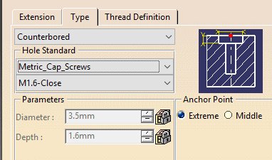
@ #7 I don't recall which release this started in, but, you now can use hole standards to define c'bore hole c'sinked holes etc in an XML file similar to thread standards. Maybe you can incorporate that.
hole_standard_g5cmup.png


Consider making this into a userform with options and toggles. Sometimes it can be frustrating to have many input boxes you have to click through. If you make a mistake in the middle you have to start all over again. Maybe have a listbox with all the input points, another section for support geometry, toggle for direction, geo-set/body naming fields and 1 ok/apply button when the user is satisfied with the inputs. You can have features to add/remove inputs and have example pictures appear. Just like a V5 command.
 
Status
Not open for further replies.

Part and Inventory Search

Sponsor

Back
Top