GoncaloPT
Structural
- Jun 9, 2020
- 24
Hello!
I'm having some issues analyzing the structural integrity of sliding window when subjected to wind pressure perpendicular to the glass panes.
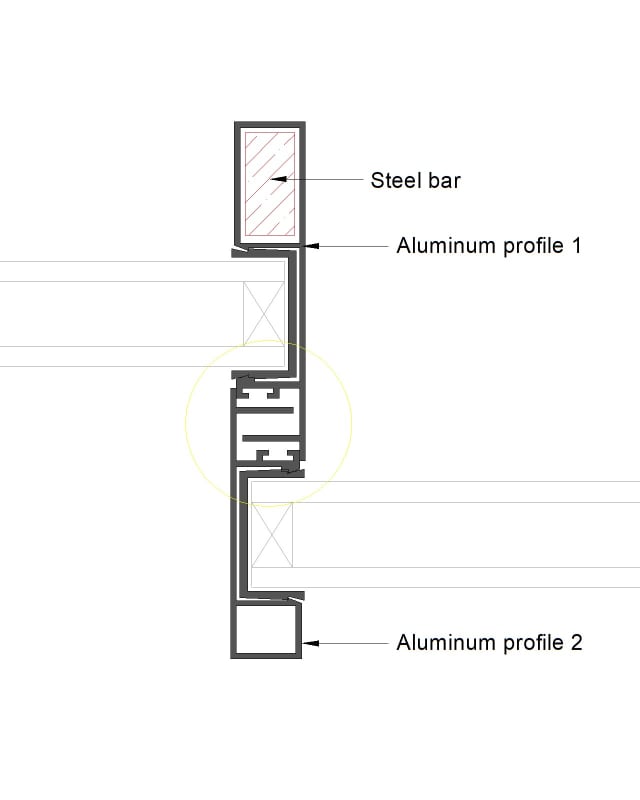
I have two glass panels supported by some aluminium frameworks profiles with a steel reinforcement bar ( see image bellow). I can take the area moment of inertia for each component individually, but i'm not sure on what to consider for the global inertia as the connection between the two aluminum profiles isn't rigid and allows for rotation between them.
I would like to get a proper deflection for the framework.
I'm also not sure on how to evaluate the maximum bending moment allowable for the assembly of the two aluminum parts and the steel bar.
Can anyone please give me some guidelines on how to proper analyse a situation like this? Any help is much welcomed.
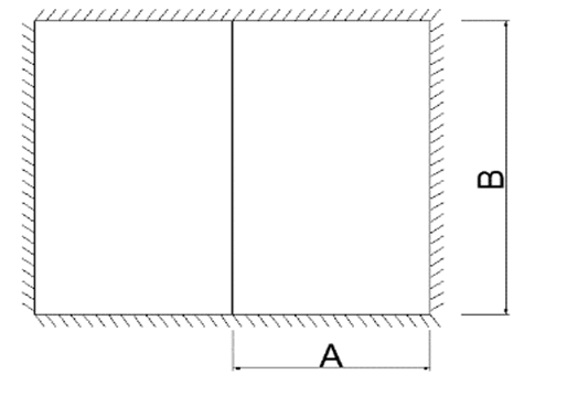
I'm having some issues analyzing the structural integrity of sliding window when subjected to wind pressure perpendicular to the glass panes.
I have two glass panels supported by some aluminium frameworks profiles with a steel reinforcement bar ( see image bellow). I can take the area moment of inertia for each component individually, but i'm not sure on what to consider for the global inertia as the connection between the two aluminum profiles isn't rigid and allows for rotation between them.
I would like to get a proper deflection for the framework.
I'm also not sure on how to evaluate the maximum bending moment allowable for the assembly of the two aluminum parts and the steel bar.
Can anyone please give me some guidelines on how to proper analyse a situation like this? Any help is much welcomed.