Continue to Site

Eng-Tips is the largest engineering community on the Internet

Intelligent Work Forums for Engineering Professionals

  • Congratulations SSS148 on being selected by the Eng-Tips community for having the most helpful posts in the forums last week. Way to Go!

Must profile be applied to a basic profile?

Status
Not open for further replies.

Belanger

Automotive
Oct 5, 2009
2,450
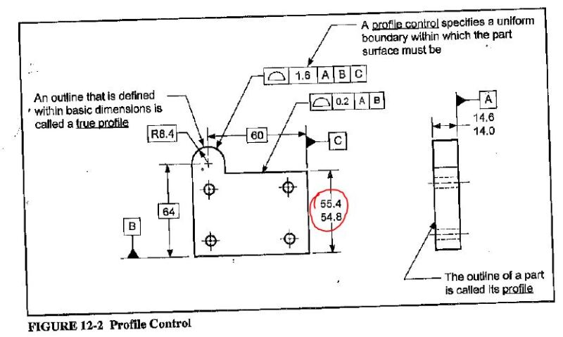
Several things have popped up in various threads that always seem to leave this question lingering: When a profile tolerance is applied, is it required for the dimensions defining the shape to be basic?
We all agree that the dimensions defining the location of the feature do not have to be basic (often they are). So please realize that I'm talking about the shape -- such as the radius of a curve: I would say that the radius must be basic if you're going to apply a profile tolerance to such a curve.

See the attached picture for the specific question to be debated. Would you say the two drawings mean exactly the same thing? Or would you say the second drawing does not comply with Y14.5?

John-Paul Belanger
Certified Sr. GD&T Professional
Geometric Learning Systems
 
 http://files.engineering.com/getfile.aspx?folder=f53db759-5cb6-4e0b-9fdd-0c44040c055c&file=Question.png
Replies continue below

Recommended for you

"Where used as a refinement of a size tolerance created by toleranced dimensions, the profile tolerance must be contained within the size limits"

I say both comply.

"For every expert there is an equal and opposite expert"
Arthur C. Clarke Profiles of the future

 
This is a point of confusion I have also have. I cannot find this wording in the actual spec but a reference book I use (Fundamentals of Geometric Dimensioning and Tolerancing by Alex Krulikowski) state:

Whenever a profile is used, it is associated with a true profile (a surface defined with basic dimensions). (Here is the part that seem somewhat contradictory) The true profile may be located with basic or toleranced dimensions relative to the datums referenced in the profile control.

He states a surface defined by basic dims but then says toleranced dims are OK. ???
This is followed by this image.
profile_xsndeo.jpg

As you can see there are both basic and toleranced dimensions.

So, as to your original survey:
1. Is OK. The part must not be smaller than 14.5 nor larger than 15.5 and the smallest actual diameter must be within the cylindricity callout of the largest actual diameter of the part.
2. I think would be OK if the diameter was not given as a max/min. With the max/min you do not know what the actual target is. Is the perfect part 15 ±0.5 or is the perfect part 15.5 with a +0/-1 tolerance. or some other non-symmetric tolerancing scheme
 
Belanger,

The important question is whether or not I can interpret your drawing.

Your Ø15.5/14.5 dimension allows the bar to be curved, or flowerpot shaped, as long as nothing exceeds the tolerances. In that context, your cylindricity forces the part to be straight and round, but it does not control the size. Your diameter tolerance is required.

On your second diagram, the profile tolerance controls the size, overruling your tolerance. Given your limit tolerancing, I claim that your nominal size is ambiguous. The dimension must be basic. I put profile tolerances on large, round clearance holes all the time. The profile controls the exact (but usually inaccurate) composite outline that I am interested in.

--
JHG
 
"Given your limit tolerancing, I claim that your nominal size is ambiguous." That is what I felt however I don't think the dim HAS to be basic.

I did find the statement regarding the necessity of "basic" dimensions.
Short answer: not required
Long answer: paragraph 8.2 of ASME Y14.5-2009, next to last sentence; Where used as a refinement of a size tolerance created by toleranced dimensions, the profile must be contained within the size limits

Based on that wording I change my response regarding drawing #2.
This is OK also. With the condition that regardless of the profile tolerance the largest this part could be is 15.5, smallest is 14.5. However the profile tolerance will always be inside the 15.5/14.5 size limit.

As in Krulikowski book, if any portion of the 55.4/54.8 surface is only 54.8 from datum B, then he furthest any part of this surface can be from B is 55.0 and the allowance to go to 55.4 goes out the window. And like-wish if part of the surface is 55.4 form B the closest any other segment of that surface can be is 55.3 and same issue with the size limit, 54.8 no longer valid.
 
djhurayt,

In a narrow, technical sense, the dimension attached to the profile tolerance does not absolutely have to be basic. I cannot see a situation where it would be anything else. Profile tolerances control just about everything. If I have a composite FCF with a stack of increasingly accurate tolerances, the profile will be on the bottom. The controls on top will be straightness, flatness, perpendicularity, parallelism or something like that, refining the relatively sloppy profile.

--
JHG
 
Both drawings mean the same... However, if there was a nominal value (15±0.5), then the 2nd drawing would be wrong.
 
Tarator ... there is no difference at all between writing 15±0.5 and 14.5-15.5.

John-Paul Belanger
Certified Sr. GD&T Professional
Geometric Learning Systems
 
Actually, there is... one has no nominal, the other one has... which makes a difference with a profile call-out...

14.5-15.5 has no nominal... we don't know where the true profile lies... it's floating, therefore you can refine it with a profile call-out.

15±0.5 has a nominal, and a true profile which is a dia15 cylinder. Therefore profile call-out would be wrong... Either, replace it with a cylindericity call-out, or change 15±0.5 to 15 BASIC.
 
@ All:

Let's take a look at the definition:

The part marked in red clearly states that Profile is intended to control FORM with or without SIZE.

It's right there: "tolerance zone to control form, or combinations of size, form..." etc.

The part marked in green clearly states that size may be controller by directly toleranced dimension.

It's right there:"size tolerance created by toleranced dimensions"

What is obviously there, but many choose to ignore it, that directly toleranced size trumps Profile.

It's actually right there: "used as a refinement of size tolerance" - in presence of directly toleranced size profile is relegated to secondary, "refinement" function.

So, if you read it together you clearly see this:

1. Size may be controlled by profile or direct tolerancing
2. When size is controlled by directly toleranced dimension, profile controls form (or orientation, or whatever)

And yes, 15±0.5 and 14.5-15.5 mean exactly the same
 
 http://files.engineering.com/getfile.aspx?folder=9355b113-bf7e-4779-bda3-b895dda45443&file=Profile_1.jpg
CH & angry bell guy,
I think you and I are on the same page. And I even thing I agree that, in THIS instance/subject matter 15±0.5 & 14.5/15.5 mean the same, but not ALWAYS.

With regard to the use of the profile callout on the OP's #2, if the diamter was a basic dimension on his drawing then the tolerance zone would be half insdie the true profile and half outside. Were as with the use of a toleranced dimension (which falls under what I said earlier and your green highlighted section) the the profile zone will always be smaller than the largest tolerance dimension allowance and larger than the smallest tolerance allowance.

OP,
I still have trouble with some of the finer details of ASME Y14.5, and you obviously based on your signature are somewhat of an expert on the subject, so, what is your take.
 
Tarator, there is no difference between 15±0.5 and 14.5-15.5. (I might agree with your last statement, but it's not because of the way the diameter tolerance is expressed.)

CH, you say that the original two pictures have identical meaning. And I hear what you're saying about par. 8.2. Then, based on your explanation, the picture I've attached would be perfectly fine?

John-Paul Belanger
Certified Sr. GD&T Professional
Geometric Learning Systems
 
 http://files.engineering.com/getfile.aspx?folder=a68e57f9-fd52-425d-b93b-9cc2b8fe131c&file=profNonbasic.png
CH, I don't understand your last post

Belanger, based on what I think we have agreed on regarding par. 8.2 (tolerance dimesnion are acceptable), I think this drawing is OK. Other than the 42 might as well be a basic dimension because the ±0.5 has no value. Due to the profile tolerance refinement of the feature, wouldn't the part be forced to fit into a 42±0.2 tolerance?
 
@djhurayt:

I'll explain.

I was arguing that size could be refined by profile, and in that sense there is nothing wrong with applying profile to directly toleranced feature. (Which doesn't mean that we should always do that)

There are also other possibilities where profile may be used together with non-basic dimensions (see the picture and note that it still about size mostly).

Belanger gives example of some taken out of context situation, which doesn't make much sense by itself. (By the way the definition of radius in standard is not perfect either).

So, I explain that my post (that has word "size" repeated 9 times) does not automatically applies to all possible combinations of dimensional/geometrical controls.

"For every expert there is an equal and opposite expert"
Arthur C. Clarke Profiles of the future

 
FORM: the ±0.1 is really not required as the profile requires the part to be 20±0.05

ORIENTATION: same basic scenario as FORM, the profile still further refine the positon tolerance of the line 20 units from datum A to ±0.05

LOCATION: probably the best dimension scheme of the four, with the 20 being “basic”, there is no question about the dimension tolerance with respect to the profile tolerance

FORM & SIZE: same as the others, other than this allows the 20 to go to 20.2 max and a 19.8 min, whereas the others restrict the max 20 dimension (regardless of a round or flat feature) to 20.1

???
 
CH, in your fourth from this post you stated: directly toleranced size trumps Profile
don't you have that backwords?
 
When you have directly toleranced size, profile doesn't control size anymore.

It doesn't have as much power as if it was controlling basic dimensioned feature.

That's what I meant.

"For every expert there is an equal and opposite expert"
Arthur C. Clarke Profiles of the future

 
Belanger,

In your diagram, anything conforming to the 0.4 profile tolerance, easily conforms to the R42[±]0.5. The radius tolerance is redundant. The dimension might as well be basic, indicating that the feature is controlled by an FCF.

In effect, the R42[±]0.5 is not wrong. It just does not provide any information.

Let's come at this from the opposite direction. I have a piece upon which I apply a profile tolerance of 0.8mm all around the outline. On one feature of the outline, I apply a dimension with a tolerance of [±]0.1mm. My assumption here is that all the applied tolerances must be met by the part. The [±]0.1mm tolerance is tighter than the profile tolerance. Parts not meeting this will be rejected even though otherwise, they meet the profile tolerance. Note how the profile tolerance acts as a position tolerances on the accurate width.

--
JHG
 
Status
Not open for further replies.

Part and Inventory Search

Sponsor