Dear all,
I am working with a newly commissioned MV/HV windfarm transmission substation that, to me, has a rather strange and arguably dangerous panel nomenclature. I hope to have some opinions from both designers and those in O&M
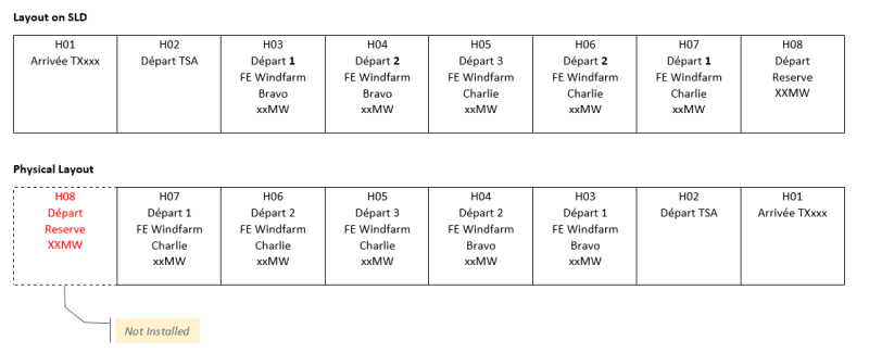
The SLD depicts a layout for panels H01 - H08 running left-to-right. Whereas the real installation has panels installed H07-H01 running left-to-right. (H08 is not installed but there is the floorspace, cable ducting and arc chute ready [but the drawing actually depicts it as installed])
There is only one incoming feeder (H01) in the MV Room but to be fair, the building has room for expansion.
They have not produced SLDs specific for switching operations but rather have an SLD that depicts power and protection design.
By my own rationale, I would have the drawing corrected to reflect the layout and the installation status of H08 (There is an A0 size print of the drawing mounted in the MV room)
They have two panels named "Départ 1" and same for "Départ 2" which to me is an unwise choice of naming. ( Read "Départ" as "outgoing feeder" [installation is in a francophone country])
The companies involved are constructing more substations and I want them to specify configurations that avoid the potential for confusion ( like when receiving switching orders by telephone.)
The Incoming feeder H01 comes from a transformer and it looks like they chose a Right-to-Left configuration because the transformer is located on the RHS of the building. I can't imagine that the apparent economy on cable length would justify setting it out like this(?) The subfloor has plenty of space for cables.
My questions
For giving switching orders, do you think the combination of these features adds unacceptable risk for personnel? (enough to request a change in the drawings, signage?)
When drawing SLDs do we as a rule of art, lay out the components in harmony with their physical layout (left to right)?
This Topic on configuration I found helpful
[URL unfurl="true"]https://www.eng-tips.com/viewthread.cfm?qid=467222[/url]
I am working with a newly commissioned MV/HV windfarm transmission substation that, to me, has a rather strange and arguably dangerous panel nomenclature. I hope to have some opinions from both designers and those in O&M
The SLD depicts a layout for panels H01 - H08 running left-to-right. Whereas the real installation has panels installed H07-H01 running left-to-right. (H08 is not installed but there is the floorspace, cable ducting and arc chute ready [but the drawing actually depicts it as installed])
There is only one incoming feeder (H01) in the MV Room but to be fair, the building has room for expansion.
They have not produced SLDs specific for switching operations but rather have an SLD that depicts power and protection design.
By my own rationale, I would have the drawing corrected to reflect the layout and the installation status of H08 (There is an A0 size print of the drawing mounted in the MV room)
They have two panels named "Départ 1" and same for "Départ 2" which to me is an unwise choice of naming. ( Read "Départ" as "outgoing feeder" [installation is in a francophone country])
The companies involved are constructing more substations and I want them to specify configurations that avoid the potential for confusion ( like when receiving switching orders by telephone.)
The Incoming feeder H01 comes from a transformer and it looks like they chose a Right-to-Left configuration because the transformer is located on the RHS of the building. I can't imagine that the apparent economy on cable length would justify setting it out like this(?) The subfloor has plenty of space for cables.
My questions
For giving switching orders, do you think the combination of these features adds unacceptable risk for personnel? (enough to request a change in the drawings, signage?)
When drawing SLDs do we as a rule of art, lay out the components in harmony with their physical layout (left to right)?
This Topic on configuration I found helpful
[URL unfurl="true"]https://www.eng-tips.com/viewthread.cfm?qid=467222[/url]