Eng-Tips is the largest engineering community on the Internet

Intelligent Work Forums for Engineering Professionals

  • Congratulations waross on being selected by the Tek-Tips community for having the most helpful posts in the forums last week. Way to Go!

My ETABS slab design doesn't look right

Status
Not open for further replies.

JoanWill

Structural
Oct 4, 2019
15
0
0
MX
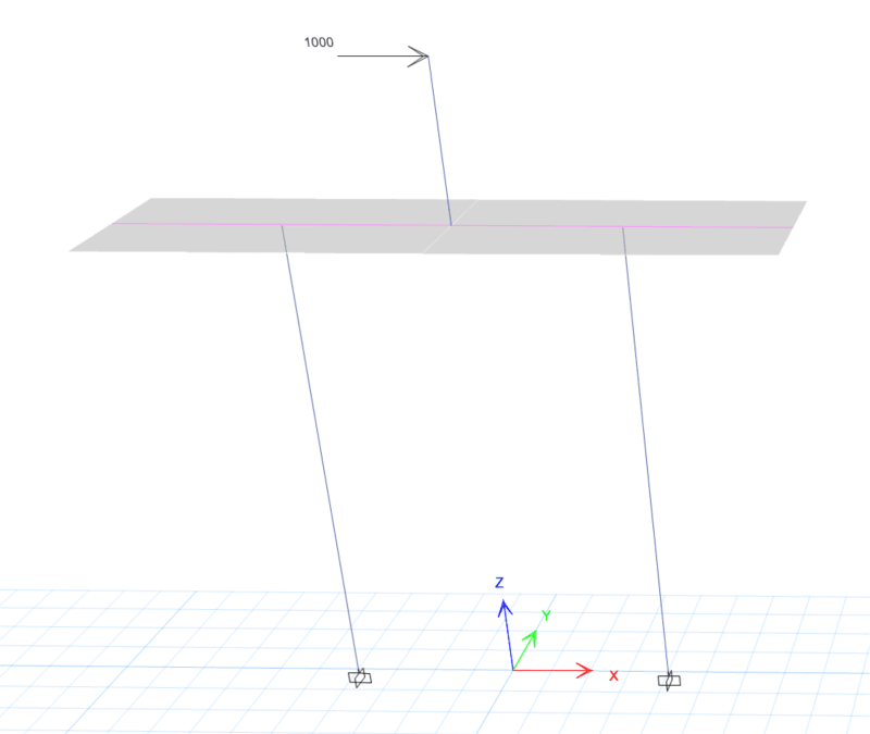
I model this quite simple structure. A 1m tall column with 1000kN lateral load on top is sitting on a 1m wide slab as you can see below.
3d_eazyct.png


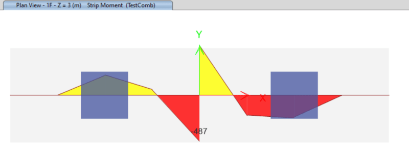
The design bending moment (-487kNm & +520kNm) in this 1m wide design strip looks normal to me. (see below)

mmm_x2p7xt.png


However, in the design module, ETABS is using about +- 1000kNm as design moment as you can see from below.

dmm_x4zr1b.png


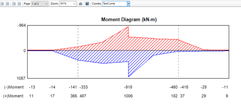
What goes wrong here? It is a simple structure so no twisting moment obviously.
 
Replies continue below

Recommended for you

Looks like the first moment diagram doesn't have gravity load but the second does. Can you make ETABS show moment diagrams for individual load patterns as a simpler verification?
 
Seems like a load combination issue. The load combinations ETABS uses to design is a separate list than all your load combinations. Go into slab or concrete beam design -> select load combinations (or something like that).
 
Only one load is shown, 1000kN on a 1m long column on top of the slab. There must be concentrated loads on the cantilevers; otherwise there would be no moment other than uniform load, which is not depicted on the moment diagrams.

Sketches are not properly explained and not fully labeled. Very confusing!
 
No. It is the same load combination. If you look at the title, they are both under "TestCombo" load combination. Gravity is not considered here, TestCombo is just 1 x Test Load Case (which is this lateral load case)
 

Yeah, 1000kNm overturning moment at the bottom of the column, which is why you are seeing +-500 kNm in the strip moment diagram.

So, 1000kN is applied under "Test" Load Case.
Load Combination "TestCombo" is just 1 x Test Load Case. No Gravity.

The second sketch is the plan view of this 1m wide slab strip showing the moment under this lateral load.
The last sketch is from the design detailed output showing what moment ETABS used for design.
 
Maybe try using Min-Max for displaying the moment. We have that option for beams, so maybe slab has that option too. Or right click on the strip when you have the moment there and see if you can play with those options and get a Min-Max in there.

I'm thinking it's just an issue of trying to figure out how to show an envelope of the moments in the program. It seems like a display/output issue, not an analysis/design issue.
 
The moment in the design strip makes sense to me. It is really just a one-way bending from my point of view. I have checked the Mmax and the integrated M1. It is the same as what the design strip is showing (+-500kNM)
 
How tall are the columns supporting the slab strip?

What does the slab strip mesh look like?

Was PDelta considered?

You have a 1000kn lateral load which the frame action and PDelta will be significant. If the slab mesh has any asymmetry then twisting moments will be generated. Any twisting with that load and the very soft out of plane, y-axis, stability will be amplified further under PDelta leading to greater twisting moment and assuming etabs is doing wood-armer would explain why you have +/- moment envelopes in the same locations.

Try adding Y axis support to the tops of all three columns.
 
Hi Celt83.
Columns below are 3m tall.
Slab meshes are just very regular 0.1mx 0.1m rectangular meshes. No symmetry. (Even if there is in the meshes the twisting moment will be very small I would say)
No Gravity has been considered so no P-Delta as well. Try to apply shear + moment directly at the slab and getting the same result so very confident to say it is not about P-delta.
Also, it is analysed in XZ plane so no restraints required for Y.

I believe the problem here is having stress concentration since the column is connecting to a certain node in the slab unlike frame analysis. But it still does not make sense because this is what design strip is for.


JoanWill said:
Columns below are 3m tall.
No Gravity has been considered so no P-Delta as well.

The axial load will be 1000(3+1)/x = 4000/x where x = col spacing; one column in tension and one in compression, so there will be a P-Delta effect. If x=4m, axial load is +/-1000kN.

 
Status
Not open for further replies.
Back
Top