Continue to Site

Eng-Tips is the largest engineering community on the Internet

Intelligent Work Forums for Engineering Professionals

  • Congratulations cowski on being selected by the Eng-Tips community for having the most helpful posts in the forums last week. Way to Go!

Nastran V9 Negative Diagonal Ratio

Status
Not open for further replies.

FireflySpace

New member
Mar 9, 2015
7
Hello Everyone,

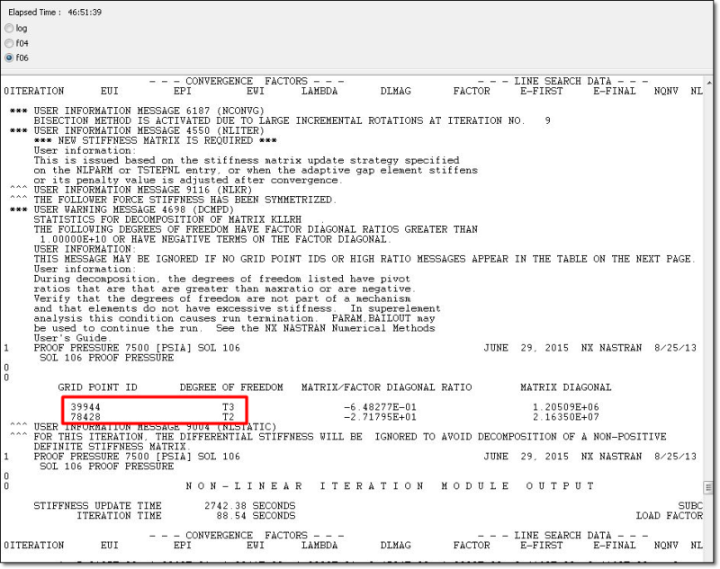
I've read thru some great responses regarding troubleshooting negative diagonal ratios & excessively large MAXRATIO, I was hoping we could take a look at my current f06 output and get some constructive feedback.

The general model:
1.) All composite pressure vessel
2.) Liner is made of plate elements
3.) The filament wound overwrap is also a plate elements
4.) The liner uses a glued connection property to connect the liner to the overwrap
5.) The boss ports at Solid elements that are also connected with glued connection properties to both the liner and overwrap

I've attached the f06 output that I am currently seeing around the .5 Load factor. I'm solving the model using NX Nastran SOL106. All thoughts and feedback are very much welcomed, thank-you kindly.

Best,
J
 
 http://files.engineering.com/getfile.aspx?folder=dad649ab-4c57-47cf-8380-b30894b84bdc&file=FEMAP_Pivot_Ratio_issues.JPG
Replies continue below

Recommended for you

Have you checked the "stability" of your model with a simple sol101 and/or sol103? both solutions will highlight any (obvious) issues (parts not attached, constrained properly, etc)
 
Yes I did, I ran SOL101 and SOL103, reviewed the model and everything seems to be in working order. I think the problem is the isotropic boss stiffness relative to the shell elements, the all-composite liner puts a larger bending stress at the boss root, and I think the model is having a hard time dealing with the plastic deformation and how the shell elements are suppose to change relative to yielding of the boss port flange... maybe... I'll need to try and run a half model, then step-up to the full 3D model
 
Hello!,
Without the FEMAP model in hand is difficult to guess the reason of the error. If both the linear static (SOL101) and modal/eigenvalue analysis (SOL103) analysis was correct, then is something related with the nonlinear (SOL106) analysis. My suggestion is to create a small PILOT STUDY to see if problem repeats.

In any case I will stidy what happens with node 39944 in the Z (T3) direction ...

FEMAP_Pivot_Ratio_issues_nvf89x.png


Best regards,
Blas.

~~~~~~~~~~~~~~~~~~~~~~
Blas Molero Hidalgo
Ingeniero Industrial
Director

IBERISA
48004 BILBAO (SPAIN)
WEB: Blog de FEMAP & NX Nastran:
 
Hi Blas Molero,

I appreciate your feed-back, I uploaded the results file... Anyways it seems to be a repeated problem with multiple models I've created. I'm going to try a few different approaches this week to minimize the contact elements.

Best,
Jared
 
Dear Jared,
This is a recursive problem I see out there many times: surface-to-surface contact "NO PENETRATION" is not supported in basic nonlinear analysis module of NX NASTRAN (SOL106), you only have the classical 1-D node-to-node CGAP element and also the point-to-line SLIDELINE contact. If surface-to-surface contact is required for nonlinear analysis then you need to use the NX NASTRAN Advanced Nonlinear solver (SOl601):

nonlinear-contact-elements-nxnastran-sol106_zpgvgq.png


Best regards,
Blas.

~~~~~~~~~~~~~~~~~~~~~~
Blas Molero Hidalgo
Ingeniero Industrial
Director

IBERISA
48004 BILBAO (SPAIN)
WEB: Blog de FEMAP & NX Nastran:
 
Hi Blas,

I apologies not getting back to you sooner, always many fires to put out. This is some great feedback, and I had a strong gut feeling telling me this was the incorrect solver to be using for these contact nonlinear high strain / displacements FEM models. Unfortunately we do not have the resources as of yet to fund the advanced solver. Something I did find interesting was that our first test article correlated to the simulation hoop and axial strains with-in a few %, the solver used here was SOL 106 with glued connections between the interfaces. I made sure that the mesh densities of the solid elements match the shell elements and things seemed to converge with out any hick-ups.

Now what I am trying to understand is why when I go to much higher pressure with thicker walls for the lay-up definition I'm getting similar (to the above screen shot) diagonal factors (small negatives) at various grid points. The only thing I seem to come up with is that even though the strain values are the same, and match my theoretical CLT calculator and Morh's circle plot, the only variation is the moments are much larger (order of magnitude higher) in the thicker walled tank, I believe Nastran is struggling to digest this.
 
Status
Not open for further replies.

Part and Inventory Search

Sponsor