Eng-Tips is the largest engineering community on the Internet

Intelligent Work Forums for Engineering Professionals

NDS Built Up Columns 3

Status
Not open for further replies.

EIT IET

Civil/Environmental
Jan 3, 2024
8
0
0
US
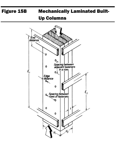
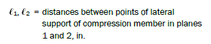
I have a question regarding section 15.3 and 15.4 of the NDS. Refer to figure 15B shown below for bracing of built-up columns (for the purpose of this question I am using 3-2x6 as the built up column and strong/weak axis are orientated respectively). My initial thought when viewing the figure/bracing is that the bracing defined by "L[sub]2[/sub]" would act as sheathing and resist movement along the weak axis of the column, and therefore bracing defined by "L[sub]1[/sub]" would resist movement along the strong axis. This assumption made sense as the weak axis would need a shorter unbraced length. However, reading the Commentary section and section 15.2.3.1, "L[sub]1[/sub] is the distance between lateral supports that provide restraint perpendicular to the wide faces of the individual members" and "L[sub]2[/sub] is the distance between lateral supports that provide restraint in a direction parallel to the wide faces of the individual members". Additionally, in section 15.3.2 (Column Stability Factor), the Kf value for built up columns (assuming 0.6 for nailed plys) is applied only when L[sub]e2[/sub]/d[sub]2[/sub] is used to calculate F[sub]ce[/sub]. This didn't make sense to me as I feel the plys would only separate with flatwise bending/buckling which would be resisted by L[sub]1[/sub]. However, the Kf value is applied for edgewise bending/buckling, where I believe the plys would act together, regardless of fastening. As I see it the Kf factor is applied to the wrong bracing. Finally, when reading section 15.4.1, looking at equation 15.4-4 where f[sub]c[/sub] is defined as less than F[sub]cE1[/sub] and F[sub]cE2[/sub], the ratio of L[sub]e1[/sub]/d[sub]1[/sub] is used to calculate F[sub]cE1[/sub], which is notarized with "for either uniaxial edgewise bending or biaxial bending". Which means the buckling design pressure for edgewise bending is calculated with the slenderness ratio defined by bracing that "provides restraint perpendicular to the wide faces" i.e. restraint for flatwise bending. The calculation of F[sub]cE2[/sub] is the same situation where the slenderness ratio defined by bracing that restrains edgewise bending is used to calculate buckling design value for flatwise bending.

Is the directionality of bracing defined incorrectly for these equations and my initial assumption was correct? Or am I misinterpreting both the column stability factor and buckling design value equations? If the latter is true, please provide an explanation/reasoning for why these values are calculated in this way.
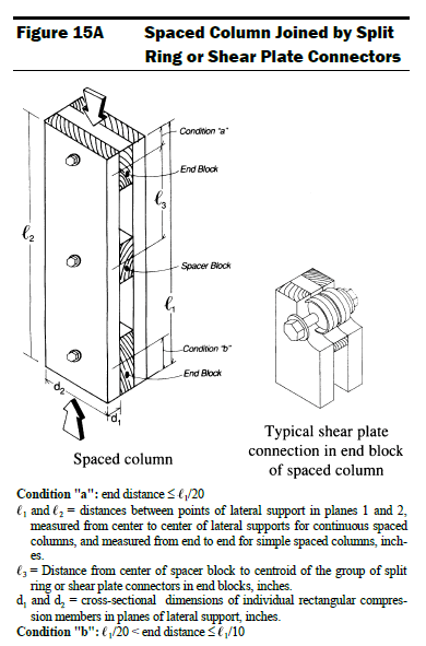
Screenshot_2024-01-03_121016_bdzkta.png
 
Replies continue below

Recommended for you

I'd say your interpretation isn't quite correct. I haven't read through the entire post, but the application of the Kf factor of 0.6 for weak axis buckling is due to the phenomenon shown in the image below, where the plies will slide overtop each other when buckling is initiated, and therefore, the member does not act as an equivalently sized single piece. NDS prescribes a 40% reduction in capacity to accommodate the incomplete composite action that develops in this scenario.

Drawing_1_ubyopb.png
 
The scenario you describe is for flatwise bending/buckling where, as I mentioned in the OP, I agree the plys would separate. However, the Kf factor is applied in edgewise bending/buckling when L2/d2 (resisting bending in the strong axis) is used as the slenderness ratio. Thus, unless I am mistaken, you have arrived at the same conclusion, that Kf is being applied in the wrong direction.
 
In the cartoon I posted, L2 is bracing interval for bracing in the left-to-right direction, which prevents weak-axis buckling. As your image shows, L2 is not preventing strong axis buckling (there is very little effect for this connection type for strong axis buckling). Strong axis bracing is provided by the L1 designation.
 
I agree with your analysis. However, The NDS defines the bracing directions as the following in reference to the Figure: "L1 is the distance between lateral supports that provide restraint perpendicular to the wide faces of the individual members" and "L2 is the distance between lateral supports that provide restraint in a direction parallel to the wide faces of the individual members" and additionally states Kf is to be applied when L2/d2 is used as the slenderness ratio.
 
Yep, that's what 15.2.3.2 states verbatim, however, section 15.2 is for spaced columns, section 15.3 is for built-up columns. If you look at Figure 15A, you'll see that L2 is switched in direction for spaced columns.

15A_rasy9b.png


Here is what I see in the definitions section, which hopefully adds a bit of clarity to the reference plane.

Capture_1_cdnxjr.png
 
Jersey, honestly, MS paint is the tool I use more than any other in my day-to-day job. I use it a lot for communicating with colleagues over the phone, in my mind, it's my favorite engineering tool that I have ready access to.
 
EIT IET said:
I see... I was applying the Figure 15A definitions to Figure 15B. Thank you for that clarification.

Of course, I don't intend to insinuate that you are in any way inexperienced, but it could be just that you are unfamiliar with the layout of this standard. I recall it took me years to really understand the layout of these standards and how to read through them at least somewhat effectively.
 
This is my first year out of college so it's fair to say I am inexperienced [lol]. I think the majority of my confusion stemmed from Enercalc applying the Kf wrong. I have done these calculations before correctly because I never read the 15A definitions and, like I said in the OP, assumed the bracing directions were applied like sheathing which was correct. However, I was verifying Enercalc's Cp value it generated and realized they were applying Kf to strong axis buckling (which is incorrect). This caused me to dig into the NDS... and we know what happened after that.
 
I don't use Enercalc, but I seem to recall you aren't the first to have issues on these forums with built-up wood column analysis in that software. I am not sure how robust their analysis methods are, but it's probably worthwhile to verify all outputs before relying on such a software suite solely. Does Enercalc have technical support you can contact for clarification? I'm curious what their response might be if there is indeed an error in their methods. Maybe they'll argue it's conservative to apply the reduction in the strong axis and leave it at that.
 
I have emailed their technical support team already and will update you when they respond. Also, the software doesn't apply Kf for weak axis buckling, only the strong axis, so even if they apply it "conservatively" for strong axis buckling, it is still incorrect.
 
With typical stud orientation you are correct if the wall is sheathed. Obviously your sheathing has to have the capacity to resist the buckling/bending forces. If you are being very precise the kL would be your fastener spacing but the other axis will almost always control so it can be assumed kL=0. If the column is orientated non-typically (usually the post must be rotated for bearing requirements of members the post is supporting) the sheathing would prevent edgewise bending.
 
This has been an issue for years in Enercalc where you have to input the factors for built-up columns yourself. Not sure why that module specifically is not set up the same as many of the others.

What I did years ago was use another program (I think Strucalc) to just make a master table of allowable loads for built-up columns for different heights. Covers like 95% of situations.
 
jerseyshore said:
What I did years ago was use another program (I think Strucalc) to just make a master table of allowable loads for built-up columns for different heights. Covers like 95% of situations.
I made a excel sheet a while ago that will give me accurate allowable loads but when loading conditions are more complicated (typically balcony connections) I like to verify with Enercalc and submit the report with the excel sheet for calc. packets.
 
I've used Enercalc daily for over a decade and that's pretty much the only module I avoid in it. Great program, but don't want to be bothered having to remember inputting that factor in that specific software only, when all the other ones already handle it for you.
 
Status
Not open for further replies.
Back
Top