EIT IET
Civil/Environmental
- Jan 3, 2024
- 8
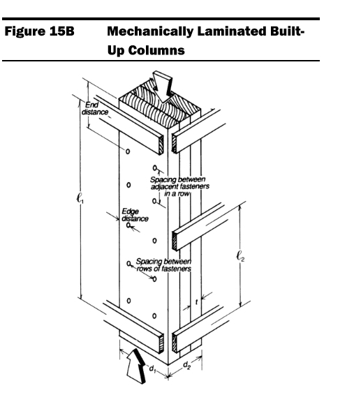
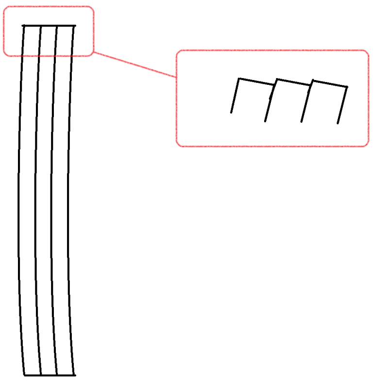
I have a question regarding section 15.3 and 15.4 of the NDS. Refer to figure 15B shown below for bracing of built-up columns (for the purpose of this question I am using 3-2x6 as the built up column and strong/weak axis are orientated respectively). My initial thought when viewing the figure/bracing is that the bracing defined by "L2" would act as sheathing and resist movement along the weak axis of the column, and therefore bracing defined by "L1" would resist movement along the strong axis. This assumption made sense as the weak axis would need a shorter unbraced length. However, reading the Commentary section and section 15.2.3.1, "L1 is the distance between lateral supports that provide restraint perpendicular to the wide faces of the individual members" and "L2 is the distance between lateral supports that provide restraint in a direction parallel to the wide faces of the individual members". Additionally, in section 15.3.2 (Column Stability Factor), the Kf value for built up columns (assuming 0.6 for nailed plys) is applied only when Le2/d2 is used to calculate Fce. This didn't make sense to me as I feel the plys would only separate with flatwise bending/buckling which would be resisted by L1. However, the Kf value is applied for edgewise bending/buckling, where I believe the plys would act together, regardless of fastening. As I see it the Kf factor is applied to the wrong bracing. Finally, when reading section 15.4.1, looking at equation 15.4-4 where fc is defined as less than FcE1 and FcE2, the ratio of Le1/d1 is used to calculate FcE1, which is notarized with "for either uniaxial edgewise bending or biaxial bending". Which means the buckling design pressure for edgewise bending is calculated with the slenderness ratio defined by bracing that "provides restraint perpendicular to the wide faces" i.e. restraint for flatwise bending. The calculation of FcE2 is the same situation where the slenderness ratio defined by bracing that restrains edgewise bending is used to calculate buckling design value for flatwise bending.
Is the directionality of bracing defined incorrectly for these equations and my initial assumption was correct? Or am I misinterpreting both the column stability factor and buckling design value equations? If the latter is true, please provide an explanation/reasoning for why these values are calculated in this way.

Is the directionality of bracing defined incorrectly for these equations and my initial assumption was correct? Or am I misinterpreting both the column stability factor and buckling design value equations? If the latter is true, please provide an explanation/reasoning for why these values are calculated in this way.


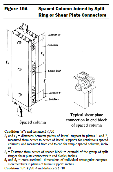
![[lol] [lol] [lol]](/data/assets/smilies/lol.gif) . I think the majority of my confusion stemmed from Enercalc applying the Kf wrong. I have done these calculations before correctly because I never read the 15A definitions and, like I said in the OP, assumed the bracing directions were applied like sheathing which was correct. However, I was verifying Enercalc's Cp value it generated and realized they were applying Kf to strong axis buckling (which is incorrect). This caused me to dig into the NDS... and we know what happened after that.
. I think the majority of my confusion stemmed from Enercalc applying the Kf wrong. I have done these calculations before correctly because I never read the 15A definitions and, like I said in the OP, assumed the bracing directions were applied like sheathing which was correct. However, I was verifying Enercalc's Cp value it generated and realized they were applying Kf to strong axis buckling (which is incorrect). This caused me to dig into the NDS... and we know what happened after that.