Eng-Tips is the largest engineering community on the Internet

Intelligent Work Forums for Engineering Professionals

Need advice on FEA settings. Result is not satisfied of required safety factor. 2

Status
Not open for further replies.

Mr_Curious

Mechanical
Jul 14, 2020
39
0
0
RU
Hi everyone [smile].

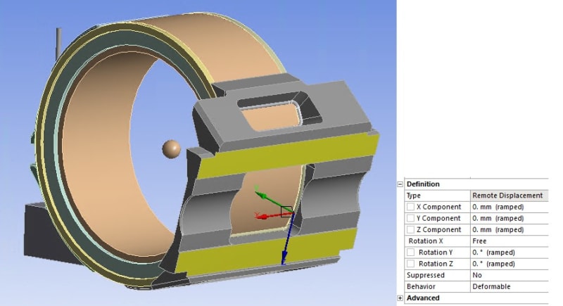
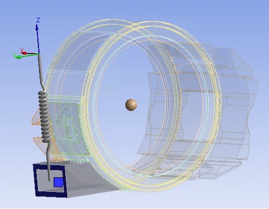
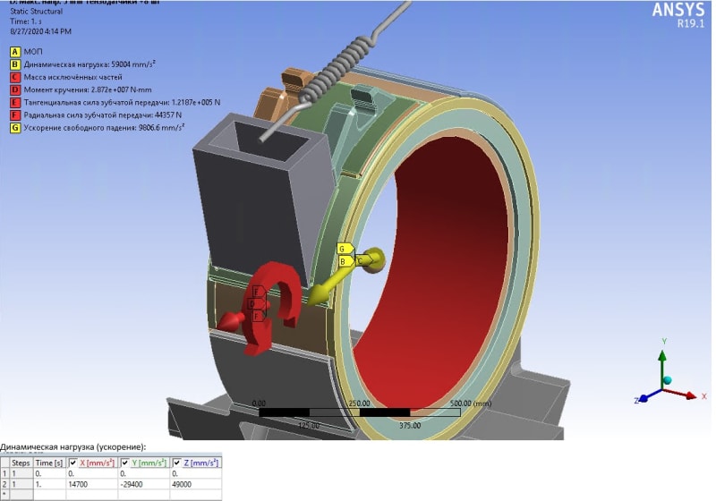
I am making stress analysis of an electric motor.
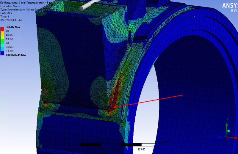
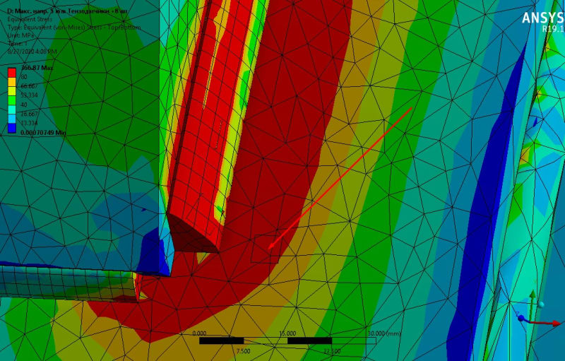
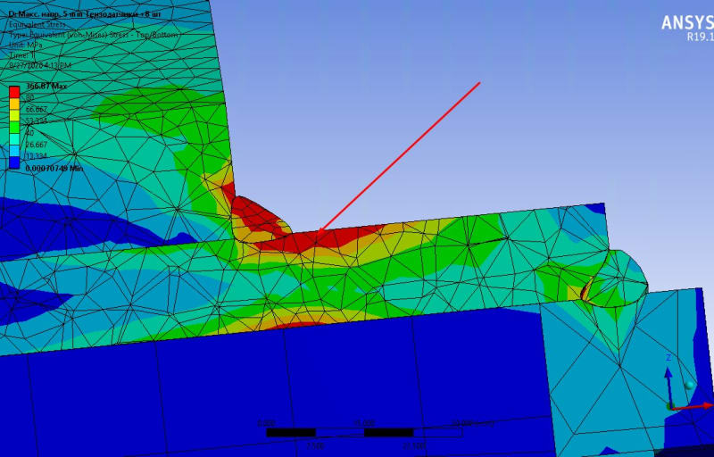
The problem is i have gotten the higest stress near the weld connection which is the reason why my construction is not satisfied the required safety factor.
The highest stress is situated at one fourth of the part depth (third picture) so i suppose if i calculate this cut by hand i will get much lower result.

I have no idea how i can try to reduce the stress. Currently i am changing the grid and if it wont help and i dont know what to do else.

Can someone advice me on what else i can do to reduce the stress at this spot?

Thanks in advance.

Stress_1_nmk0tw.jpg

Stress_olxnz0.jpg

Stress_3_yoshxc.jpg
 
Replies continue below

Recommended for you

When you include the welds’ geometry in the model, you should make sure that the mesh is properly refined around them. Perform convergence study to determine the necessary mesh size in this region. Also make sure that welds are properly connected with the rest of the model.

Can you show the whole model with boundary condition and load symbols ?
 
Refine the mesh in the region of interest and run the analysis again to see how the results change with denser mesh. Repeat several times until the difference will be negligible. You can create a plot of max stress vs element size to make it easier.
 
The recommended method of mesh convergence I've seen in most texts is to half the element size in the region of interest and check if stress changes <10% if yes then good, if no refine further. Looks like your weld is its own solid (non-coincident nodes with nearby structure)I can't say for sure how ANSYS connects dissimilar meshes, but in FEMAP/NASTRAN this would be a glued connection and I would argue that the stresses near a glued region are not accurate. I would typically do a hand calculation based on Blodgett's formulas for the weld and only use the FEM results near the welds for ballpark comparison.

Edit: I would also add that is a fairly good sized chunk of red you have there, could be something to this more than inaccurate weld modeling. Have you considered your part is yielding and you might need a bigger weld / better geometry? I would be uncomfortable using non-linear analysis to prove a weld good unless you are really an expert. Analyzing welds in FEA is an advanced topic. Another consideration, will you have repeated loads on this part? Fatigue could be of concern as well depending on use.
 
I made the grid smaller and larger and got a results that differ by 10%. But i need at least 40% decrease. Now I am trying to perform convergence and wtite results later.
 
Convergence is not a tool used to decrease stress results! Mesh convergence studies are used to verify the mesh is accurate enough for engineering approximation! Usually you will see stress results increase as your mesh trends towards convergence. Your part is likely over-stressed
 
Nonlinear analysis doesn’t have to mean nonlinear material. It may just account for geometric nonlinearity. In fact it’s often interpreted this way by FEA software users because geometric nonlinearity activation is usually done by checking appropriate box in solver settings.
 
Gordievsky said:
Currently i am changing the grid and if it wont help and i dont know what to do else

You don't change the mesh until you get the result you want, you change the mesh until it's accurate. I'm confused why others are giving advice on non-linear FEA with this level of misunderstanding of the finite element method in the original question.
 
You're right MS, I think there is limited knowledge/experience with the OP. That is not a dig at the OP, he's come here asking for help.

There's a lot going on in his model … clearly area contact, modelling a weld (the weld material) is something I wouldn't do (I'd do some hand calc).
Presumably the material properties of the weld material are right ? and the local heat affected zone ?
There so many things we can't really see. Constraints seem to be a couple of arrows … which makes me think of fixed constraints, which is scary.

But the usual answer to localised stress peaks is NL (ok, material nonlinearity). Sure, you could do some "neuber" analysis with linear stresses (can you apply neuber to a weld ?).

another day in paradise, or is paradise one day closer ?
 
I am a civil engineer so my comment might be inappropriate. I notice that your model assumes that the weld does not turn around the corner, which creates a sharp change, discontinuity, in the model. How realistic is this assumption? Can you modify the construction/design in a simple way rather than tweaking the model?
 
In addition to high stress in the weld, it looks like the pad on the shell is highly stressed in bending. If this isn't acceptable, make the pad thicker to keep the bending stress at an acceptable level.

To decide if it's acceptable, you need to elaborate on what you are trying to prevent. Are you designing for a single overload failure (collapse) or fatigue? If overload failure and you have a ductile material, plastic analysis is definitely the way to go. Do you have a safety factor against collapse you need to meet? Is there a deflection limit? These things are straightforward with plastic analysis. If you are designing for fatigue with welds, I'd stick with elastic and look into a structural stress method.

I'll also second the comment above about mesh insensitivity. The results must be mesh insensitive or else they are meaningless. Personally, I find rules of thumb like <10% change to be unreliable unless the analyst has significant experience. For a novice, I'd shoot for a much greater degree of insensitivity.

-mskds545
 
A tangential but hopefully helpful note about convergence:

How many points will it take to fit a continuous sinusoid (one frequency/one period)? Two? Four? Ten? Look up Nyquist criterion if you do not know the answer. Intuitively, you know you will need "sufficient" points for the discrete sinusoid. In other words, the more points you sample the sinusoid, the closer the discrete sinusoid will look to the continuous one. If you have too few points, then the discrete version will look strange. This phenomenon known as aliasing is observed in real life when spinning objects like ceiling fans, tires, etc. appear to moving slow or even in the opposite direction. It happens because the sampling of our eye is too slow in time.

When you solve a discrete system of equations numerically, you are trying to compute various spatial fields of interest (displacement, strain, stress, etc.) over time. These fields may be represented as a combination of sinusoids so, as in the example above, you want to be sure you have sufficient number of sampling points (nodes) so that the quantity of interest is effectively independent of the mesh i.e., it does not vary "by much". You want to do the same thing over time as well, if time is taken under consideration. Note that just because you got a converged solution for one quantity of interest in one model, you cannot say the same about other fields from the same model or a "slightly tweaked" model.

Unfortunately, the more you dig into it, the messier it becomes but the discussion above is sufficient for a majority of practical purposes especially when the risk profile (due to modeling prediction) is low. If you are mathematically inclined and interested to know more, papers by Roache, Oberkampf and Roy might be good to look at.

*********************************************************
Are you new to this forum? If so, please read these FAQs:

 
Status
Not open for further replies.
Back
Top