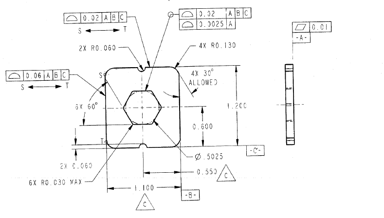
The leaderline profile is indicating the side which applies. In between points S and T profile applies for 3 of the sides within one tolerance zone and another profile applies within the other tolerance zone.
Burunduk, that's not strictly a pre-1994 drawing. The datum feature symbol is certainly from 1982, but the "between" arrow didn't exist until 1994! So it looks like a hybrid of Y14.5 standards.
There is no significance to the order as the leader indicates the portion it applies to. Otherwise it becomes a hassle of the clockwise little-endians and the counter-clockwise big-endians.
Belanger,
Good point.
Still a decent drawing in my opinion. Don't you think? Compared to what is usually out there...
Another thing that slightly bothered me about this drawing, is what exactly datum feature C? The natural choice would be to use both coplanar features that are interrupted by the bottom slot, but as it is shown - there is no indication of it, and the "official" interpretation would be that datum feature C is only the right bottom surface, do you agree?
Yes, the MAX and "ALLOWED" are out of place when they are within what should be a basic true profile definition for an all-around or "between" control. Good catch also.
I have an idea what they might be trying to convey with the MAX but I still have two possible interpretations, partly depending on if that Radius is actually illustrated or if it's shown as a corner (hard to tell with that line weight). As far as the "ALLOWED" I think they were trying to convey it as an alternative to the corner radii. In both cases I'd just ask rather than assume my interpretation is correct.