Eng-Tips is the largest engineering community on the Internet

Intelligent Work Forums for Engineering Professionals

Need Introduction to Die Design

Status
Not open for further replies.

pancakeglutton

Mechanical
Aug 3, 2023
7
0
0
CA
Hey guys! First time poster here. Need some help in designing a forming die for a curved angle. Please see photos below.

Curved_angle_u2tocv.png

Curved_angle_2_acqay7.png


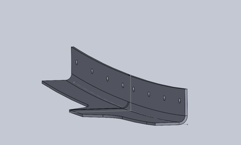
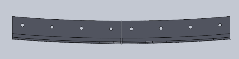
This is a part used to splice two other sheet metal parts together. We intend to use a press brake to form this part, so we will need a set of dies and a flat pattern to make this efficient. We are not making a couple thousands of these, so that's why we don't want to use a roll former.

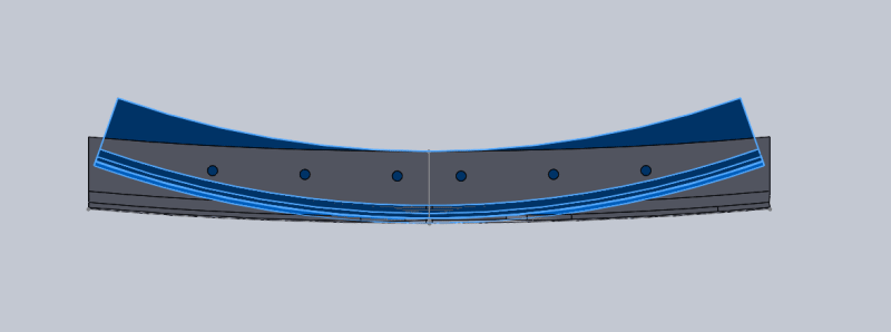
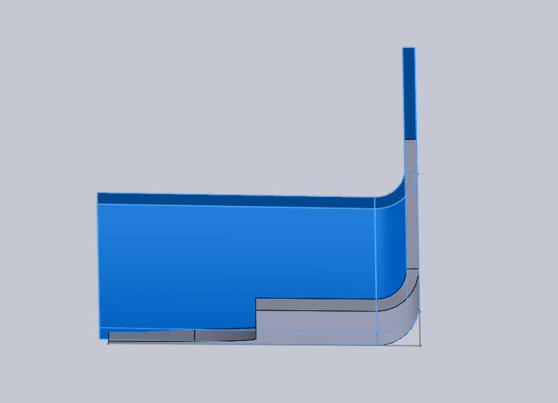
Currently I used a online sheet metal springbuck calculator to calculate the radius I need for the big curve on the die and the bend radius for the flange. Assuming that the neutral line in both bend directions are in the middle of the thickness of the sheet, I then draw arcs that are of the same length as the neutral lines, but of the radii I got from the calculators plus half of the sheet thickness. So I now have a die form that accounts for spring back. The die form is highlighted in the photos below.

Curved_angle_die_form_wjcwai.png

Curved_angle_die_form_2_hupmed.png

Curved_angle_die_form_3_wymp7q.png


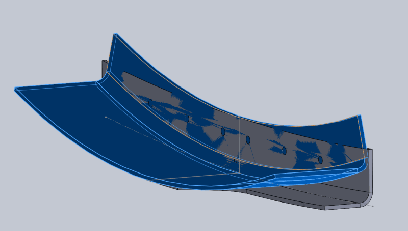
I have three questions:

1) Am I roughly on the right track in designing this die form?​
2) Due to the shape of this part, do I have to tighten the big curve more on the die form to account for the flange that will have holes on the finished part?​
3) Can I add the holes onto the flat pattern without them deforming?​

I'm very new to die design. In fact I have another 3 sets of dies I'm working on for some different parts that I had been working on for over an year now. Still not quite right. So help with whis particular one would be much appreciated. I've attached parasolids of the part and the die form if anyone wants to look at them in CAD.

 
Replies continue below

Recommended for you

Hey 3DDave! Thanks for the reply. That is how they made the part for our prototype installation. They bend it and then use the shrinker. I forgot to add that we are starting from 7075-O and then tempering to T62 after forming. Do you think it is not worth our time to make a die? We're looking at, let's say around 150 of these.
 
A die is typically useful for 10,000+ copies. An intermediate solution (~1000) would be welding, but for 150? Either a shrinker or a roller to form it. The roller has a slot that captures the vertical leg and forces it to remain fairly straight - is a home-made adapter.
 
pancake

look at youtube for rubber type of dies, very simple and economical. also allow for setback and spring back.
google that. 150 parts a simple die will do
 
I did not review your models to determine part size and bending forces needed nor quality requirements (needed to determine tooling precision requirements). If forces are not great and tolerances are forgiving, then there are a number of ways to hack 150 units.
[ul]
[li]machining dies (made of soft materials) for use in a small shop press: video shows pipe bending but principle is same
[/li]
[li]roller bender machines, but then it becomes less production and more craftsmanship (find a shop with a roller for prototyping services)
[/li]
[li]there are 3D printing technologies and materials out there that can be used to print dies that will survive a small number of cycles (perhaps as many as 150 or more?)
[/li]
[/ul]

TygerDawg
Blue Technik LLC
Manufacturing Engineering Consulting
 
To me, there are fabricators who could take this on and provide you with parts. You did not provide a dimensioned sketch, so I have no idea the size of these. If I was starting on this from scratch, I would contact someone like Chicago Metal Rolled Products. A bending operation and subsequent laser trimming seems like one way to accomplish this. I imagine someone in this industry could get you the parts you want. You might even be able to pay a visit to the fabricator and watch them create your order to see how it is done. The companies that I have worked for have bending machines that can form beam, channel, angle, and bar - typically cut long with straight section at each end, and trimmed to meet dimensional needs. Chicago Metal Rolled Products has a link to a nice AISC design guide.
 
Hey guys! Thanks for all the good suggestions. I'll try and provide more context in this reply.

The angle is to be made out of .050 thick 7075-O material and then heat treated to T62 after forming. The two ends of the part are parallel and measures 6.62 in length. The vertical flange is 0.7 tall where as the horizontal flange is 0.67 mostly, with the tab at 1.27. I think we will need a .030 wide profile tolerance on the horizontal flange since this does have to conform to the contour of the part this angle sits on pretty well.

We are familiar with rubber press form as we are using this process to form some frames in this project. The dies we are using are not of my design and the people who designed them are all gone. In fact the dies were really for hammer forming. We have also tried 3D printed tooling. We have printed some with ULTEM 9085. They don't fail ductile, so they get a bit explody when they fail.

The question I have is really how do I get a good starting point with the springbuck to avoid having to go through, let's say 5 iterations of the die.
 
I found the thread with the word "press brake". Depends on real thickness and geometry probably could be done with press brake and special tooling. What thickness is this and what model of press brake you do want to use? If I will be you I will think about special punch to produce and bending into polyurethane if the part is less than 1,5 mm thickness
 
to mfgenggear
Sure thing agree that cheap and ok if enough the pressure of press. For sure everywhere the question about parts quantity - it is the method for single parts production, not hundreds or thousand. And you are correct - real hydroforming is incredible expensive machinery
 
Status
Not open for further replies.
Back
Top