Continue to Site

Eng-Tips is the largest engineering community on the Internet

Intelligent Work Forums for Engineering Professionals

  • Congratulations cowski on being selected by the Eng-Tips community for having the most helpful posts in the forums last week. Way to Go!

Need some guide on irregular 2 way slab design 2

Status
Not open for further replies.

BeckSt

Structural
Dec 29, 2019
4
It is my first time to design irregular 2 way slab and I need some help from you.
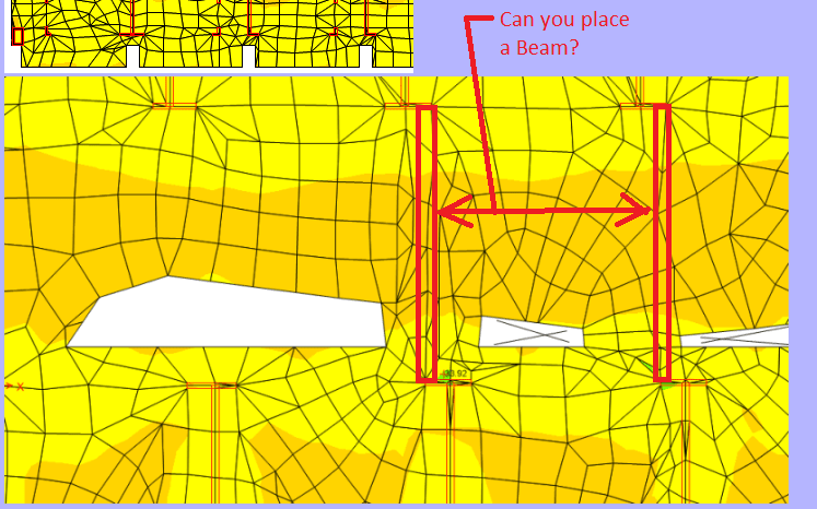
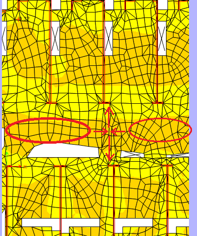
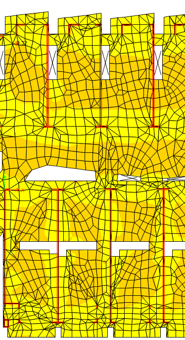
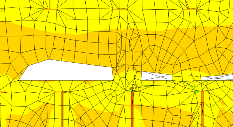
I have used FEA for the slab analysis and below is the shell stress. Most of the stress is less than 3 MPa. but I have noticed that the stress in some mesh is greater than 35MPa (the green ones). Why is that? Is it more because of the model error? (There is only UDL on the slab. no point load added)
Also. what books do you guys recommend for slab design? I am not very confident in arranging the reinforcement correctly. Can anyone provide some resource for irregular slab design example including the reo arrangement after analysis? Thank you very much.

23_ytxz8h.png

34_kmzkfo.png
 
Replies continue below

Recommended for you

What are those red lines represent, steel beams/colimns?
 
I have never designed a slab using anything so sophisticated as FEA but I am impressed.

I think the red lines represent walls but the slab seems to have some very strange shapes for openings (white spaces).

BA
 
Have to echo what BA said about those openings.....the word constructability comes to mind. Not that it can't be done.....but would be quite a challenge.

In any case, to answer your question.....what you are referring to is most likely a stress concentration. They occur because of geometry, supports, etc. Assuming those red lines are walls, it most likely is because of that.

For the 2 way reinforced concrete slabs I have done in the past, I typically have based my design on moments and shear stresses from the analysis. You can justify the force "spreading out" (i.e. smoothed) based on how wide spread it is and the geometry of the situation.
 
Agree with WARose likely seeing stress concentrations.

With the irregularity of the slab layout and openings I'd also say the mesh you have shown is too coarse and needs some refinement. Be careful with those stair openings in the middle of the units, especially the L shaped ones, FEM may say the slab is OK but for serviceability considerations these likely want to be framed out with beams.

Open Source Structural Applications:
 
For analysis, could you 'square up' the irregularly shaped openings and then come up with a reinforcement design that works.

After that, do localized analysis of the irregular shaped regions and add reinforcement as needed?

We do a similar procedure on bridge columns that have lots of added aesthetic elements. We will design a basic square or circular column. Then just add the aesthetic stuff on top. In finite element language, I would call it a 'lower bound solution'
 
In my opinion, you shall try refine your model, so the majority of elements will conform to orthogonal grid system (xy, or xz plan), and only use triangular and irregular elements at locations that couldn't avoid. Use finer meshes near rigid elements, such as column, wall, etc., and coarser element at other locations, but always maintain good aspect ratio. Otherwise, your analysis will be quite difficult to interpret, yet to be used for real design. The color will be quite impressive though.

Also share the same concern with the others, what happened for the irregular shaped openings, by design, or modeling errors?
 
I think that young Engineers have a desire to jump right into analysis using FEA tools but unfortunately don't have much of a game plan beyond that.

1. How are you relating the stresses you are getting from the program to a force based design approach (ACI, etc...) As structural Engineers we are not normally stress analysts. Concrete is an anisotropic material that doesn't really behave in a manner that is conducive for a stress analysis. I have done what you are doing before for concrete slabs, but typically to prove that the stress is below the modulus of rupture and that the slab (theoretically) has not cracked.
2. If you are going to try and run this approach for design, I hope your FEA program allows you to "slice" the shell elements across a width to produce the equivalent forces (bending moment, shear, etc.) The programs that we use in our office, LUSAS and Midas Civil will integrate for you to produce the results. Otherwise you are going to have to do it by hand. If you are going down that path, you are doing too much work. The other question that you will have to decide on is how wide of strips are you going to analyze and design for.
3. Are you displaying the Von Mises stress for the slab? In looking at your model, I'm not surprised that you are getting such high stresses at that location. It looks like the slab in that location is acting like a strong band. There is a lot of load that is being resolved at that point. Can you put a beam between the walls? See attached.
FEA_c1toqa.png

The stress, however, is probably not accurate since your mesh is not refined enough at that location to capture the true stress concentration.
4. This is a perfect example why many Engineers opt not to use FEA to solve a problem like this and rather try and simplify it with more basic equations. i.e. strong and weak bands. FEA is nice to see where the highest stress concentrations are but it doesn't really make the design and detailing any easier. This is a good lesson though. Is this a PT slab? Flat plate?
 
Thanks for your replies.
The red lines are walls under and the white areas are openings. It is a flat slab.
I am not a big fan of FEA and I normally do traditional computation for slabs but when irregular slab can't be avoided I don't know what simplified method can be used in lieu of FEA. And that's why I am trying to re-analyse and understand the results from FEA. As for the stress concentration, can you elaborate on why it happens to those two meshes only as other meshes at slab-wall connections seem 'fine' ?
These irregular shapes are as per architects' dwgs. Unfortunately I can't place beams like what STrctPono suggested as you can see the walls above and below don't always line up and some voids are just located in between walls, which make it impossible to place beams linking walls above and below.

I also have a simplified question regarding this, how do you analysis the following simplified slab?
55_pk4uql.jpg
 
What software are you using to design this slab? I would never use a general FEA package for concrete slab design. You need specialist software such as RAM Concept that is able to make allowance for Mxy stresses, check punching shear and (most importantly) calculate long-term deflections including creep and shrinkage effects.
 
I am using Etabs at this stage and will later move to SAFE for long term deflection. At this stage I am just checking the stress for strength purpose.
 
Hi Celt83, May I ask why long term deflections SAFE underestimated in SAFE?
 
BeckSt:
There was something off with one of the components of the long term derivation that needed user manipulation to get a reasonable result, this was about 8 years ago so it is likely that a correction has been applied but probably worth reading their current documentation on long term deflection to verify their procedure.

Open Source Structural Applications:
 
I'm not very familiar with SAFE but I understand it can do all the strength calculations for you. CSI has a series of 12 video tutorials on YouTube. I suggest you work through them.

Checking the shell stresses from the FEA output won't tell you much as they are probably based on gross uncracked section properties. You'd be better off looking at the moments and shears.
 
For the slab design I absolutely recommend SAFE. I've used it in the past - great program. It allows you to easily switch between a strip based and FEA based analysis and design. Be careful using it, though. It's very powerful and not exactly user friendly if you've never touched it. I was fortunate to have another engineer in the office sacrifice his lunch breaks for a week or two to teach me the ins and outs. I compared a model I built to "try it out" to the same model after learning how to actually use the program - results were night and day. Plenty of settings to misuse or miss altogether.
 
It appears that your stress concentrations are occurring on poorly meshed portions of your structure. A common theme is that your mesh elements with high stress are triangular, similar to a pie slice when someone asks for "just a tiny one". Because of the narrow element and the sharp tip of that element, stress concentrations are occurring at that location. Any mesh generation instruction text will discuss this pitfall of triangular elements.

I don't mean to provide a lecture on the intricacies of FEA, as that already exists on these forums in many other threads, but I will say this: mesh generation is fundamental to the accuracy of your results. There are many good resources online, and often from your software provider, that give advice on mesh sizes and shapes. Just looking at the images provided, I am willing to bet that your mesh was automatically generated by the analysis program, and I have to say that it didn't do a spectacular job of it.

I am not sure if ETABS can import a mesh, or if you are forced to use its own mesh generation tools? If you can import a mesh, then you may want to look for a better mesh generation tool to help you get this complicated shape more accurately modeled. Otherwise, using the program's own mesh refinement tools would be adviseable to avoid these "thin pie slices".
 
The mesh used looks coarse for a stress analysis of slab. I would tighten the mesh parameters to clean up the element shape / aspect ratios.
 
Pay close attention to your slab length to width ratios. With all of those openings, you may get the full benefit of two way action that you think you're getting. You may also want to design "beams" within the slab to transfer load around the opening. Is this slab also acting as a diaphragm?
 
Even if he tightens up the size of his mesh and changes his triangular to quadrilateral elements (which I agree with you all), there is still a significant amount of load being dumped from the surrounding slab into that one narrow band of slab that spans from one end of the wall to the other. Most of the other slab actually seems to be behaving like a one-way slab.

Untitled2_ywrgxj.png
 
Status
Not open for further replies.

Part and Inventory Search

Sponsor