Continue to Site

Eng-Tips is the largest engineering community on the Internet

Intelligent Work Forums for Engineering Professionals

  • Congratulations cowski on being selected by the Eng-Tips community for having the most helpful posts in the forums last week. Way to Go!

Need the Latest Design Guide for this HSS connection?

Status
Not open for further replies.

Ron247

Structural
Jan 18, 2019
1,142
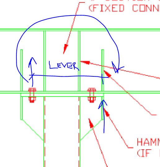
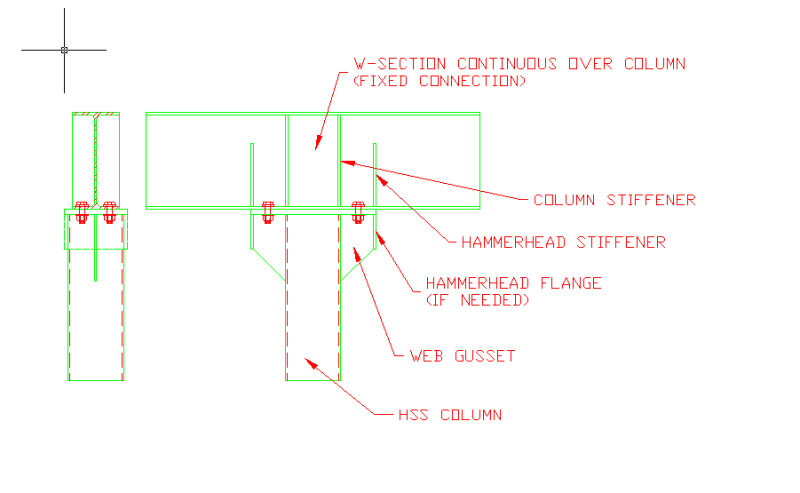
I have an old spreadsheet I am trying to bring into the 20th century. It is for an HSS column that is fixed to a W-Section. What is the latest guide on the design of this connection? The only thing I see after a quick internet search is the second image below. It is for a shear only connection and not a fixed connection. The first image is a generic detail of what I am trying to do and there are portions of it that may not be in every design. Everything else I find on the internet has the W-section framing into the side rather than across the top.

Any help would be appreciated. I am not up to speed on the LRFD methods but it looks like I am going to have to learn them. I am especially looking for the current way of checking the web gusset to the HSS versus a through plate.


HSS_Col_to_W-Flange_Bm-Fixed_o1cwnn.png


HSS_Col_to_W-Flange_Bm-pinned_rnni2c.png
 
Replies continue below

Recommended for you

Are you married to that connection style? It's pretty bad ass but it's not one that I've ever seen in print. If you want it just this way, you/we might have to feel your way though the load path first principles style.

HELP! I'd like your help with a thread that I was forced to move to the business issues section where it will surely be seen by next to nobody that matters to me:
 
This is the one that I see most typically. Obviously, yours is more convincing.

c01_t5qwqg.jpg


HELP! I'd like your help with a thread that I was forced to move to the business issues section where it will surely be seen by next to nobody that matters to me:
 
KootK said:
Are you married to that connection style?

LOL. Thankfully, I am not married to it, but we have dated a long time.

The gussets and hammerhead flanges are what I have had to use to reinforce an existing splice that appeared incorrectly designed. I do some rehab/repair projects. For that reason, I put the calcs in my spreadsheet for that. I do not think I have ever had to do one as new construction. I have had to add them to a new design I did because the fab people got the plate thickness wrong one time but had already fabbed all the columns and erected them when I noticed the plates looked too thin. We had a standard note about capping all tube and pipe columns with a 1/4" plate UNO and someone took that to mean even the splice plates.

Thanks
 
KootK: In your sketch, is Cr at the inside face of the section thickness? I am assuming the distance from Cr to 2T is your moment arm? When I add the gussets and hammerhead, I have to calculate the new NA.
 
Ron247 said:
The gussets and hammerhead flanges are what I have had to use to reinforce an existing splice that appeared incorrectly designed

Ahh... I see.

Ron247 said:
I am especially looking for the current way of checking the web gusset to the HSS versus a through plate.

Your issue would then be the tendency of the gusset to push into the HSS walls and yield them in complex ways. The guide below is probably a solid resource but I'm not sure that even it covers your exact situation with respect to the delivery of a localized moment. Baring better info, I'd be inclined to just envision a horizontal strip of HSS wall resisting the inwards thrust and design that to deal the bending. That face could be reinforced as needed. Heck, you could use wide flange chunks in place of the gusset and probably get your reinforcing that way. You know, space and aesthetics permitting.

CIDECT Manuals are good too but I don't know that they're any better than AISC. It's same, incestuous gaggle of professors working on all these docs. Dr. Packer is a University of Toronto rockstar no less.

c01_tfya0j.jpg


HELP! I'd like your help with a thread that I was forced to move to the business issues section where it will surely be seen by next to nobody that matters to me:
 
Ron247 said:
In your sketch, is Cr at the inside face of the section thickness?

The middle of that wall would probably be most accurate. But, given the uncertainties involved, I'd not bat one of my luscious eyelashes as using the inside or outside faces of the wall.

Ron247 said:
I am assuming the distance from Cr to 2T is your moment arm?

Yesir.

Ron247 said:
When I add the gussets and hammerhead, I have to calculate the new NA.

A) How do you do that?

B) For what purpose do you do that?

I'd think your moment arm as shown below.

c01_hwyayg.jpg


HELP! I'd like your help with a thread that I was forced to move to the business issues section where it will surely be seen by next to nobody that matters to me:
 
KootK said:
Heck, you could use wide flange chunks in place of the gusset and probably get your reinforcing that way

I had not thought of that. I may add that to the spreadsheet too. Probably easier to calculate than the gusset and hammerhead. The gusset and hammerhead is when I have limited splice plate length to deal with. I could notch the W-section chunks around the plate if needed. The added steel shifts the NA, lowers the bolt load and allows the load to be dispersed to multiple locations.
 
For the yieldline assessment part of assessing the end plate and flange capacity both P207 and P398 from the SCI in the UK are good resources, I posted a link to both yesterday in this topic.
 
Well for starters they seem to be two different connection types. The top one being a moment connection and the bottom one being closer to a pinned connection.** They suit very different needs and incorrect specification can lead to problematic results.

**I say closer to a pinned connection. But it clearly can transfer some moment. I've seen the results of this type of connection causing light columns to bend like bananas. The engineer had modelled it all as pinned yet the connection clearly has some stiffness and the column was bending before the single story roof was put on.


(The assumption of a pinned vs a moment connection can potentially be quite problematic with REAL connections. A conservative approach I've found sometimes is to model both to model both and if need be model the connection stiffness.)
 
I appreciate that you area working to different design codes, but have you considered Eurocode 3 (EN 1993) Part 1-8. There is also a publication by CIDECT (Comité International pour Ie Développement et l’Étude
de la Construction Tubulaire) : DESIGN GUIDE FOR RECTANGULAR HOLLOW SECTION (RHS) JOINTS UNDER PREDOMINANTLY STATIC LOADING (apologies for upper cases, it is copy and paste). While not strictly speaking applicable, they might give you some insight into how to treat your connection.
 
The Steel Tube Institute used to have a set of spreadsheets for the design of hss-wf moment connections that were made available to designers (free at one time I think). A search for STI Hss-wf-moment-conn seems to pull up some results, although I cannot seem to navigate to them on their website directly..

I cannot remember how rigorous the design modules are, but it might be a good reference.

 
KootK said:
A) How do you do that? B) For what purpose do you do that?

I calculate the NA similar to concrete reinforcing calculations where you have the tensile steel area and the compression block area. The difference is that it is not a rectangular stress block but rather one that follows the footprint of the steel that is in compression. It may take some time to find my original source for the method since I have not looked at it in about 30 years. The spreadsheet I use is protected so I will also have to find my original spreadsheet from the dark ages. As I recall, the method is somewhat similar to some work by Eli Czenrniak. It may take me several days to find the information because we are taking a few days off.
 
Human909: They are different connection details. I was just showing that the 2nd one was all I found and it is definitely pinned in design.
 
Thanks for the help everyone. I have some of the suggested sources and am reviewing them now.
 
Status
Not open for further replies.

Part and Inventory Search

Sponsor