Eng-Tips is the largest engineering community on the Internet

Intelligent Work Forums for Engineering Professionals

Need to calculate Torque on a plug weld 1

Status
Not open for further replies.

MECH-DESIGNER

Mechanical
May 24, 2022
3
0
0
US
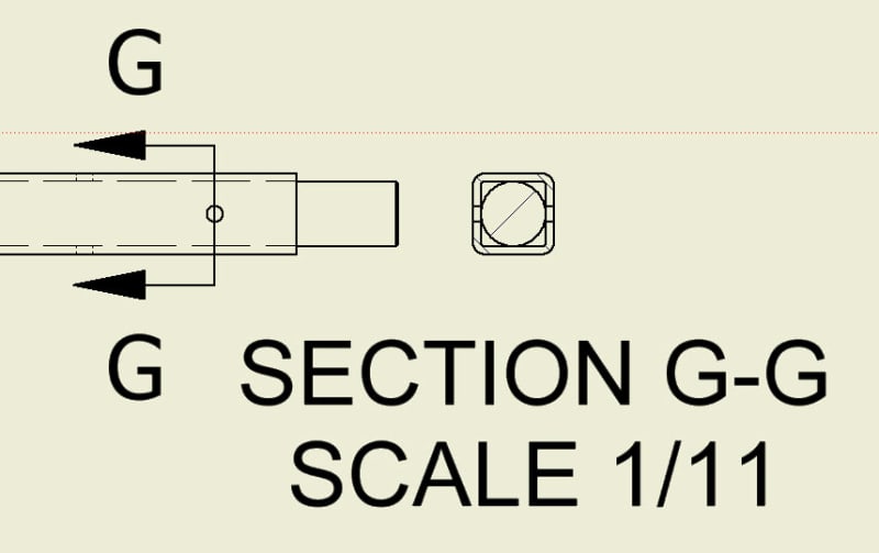
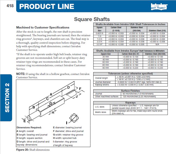
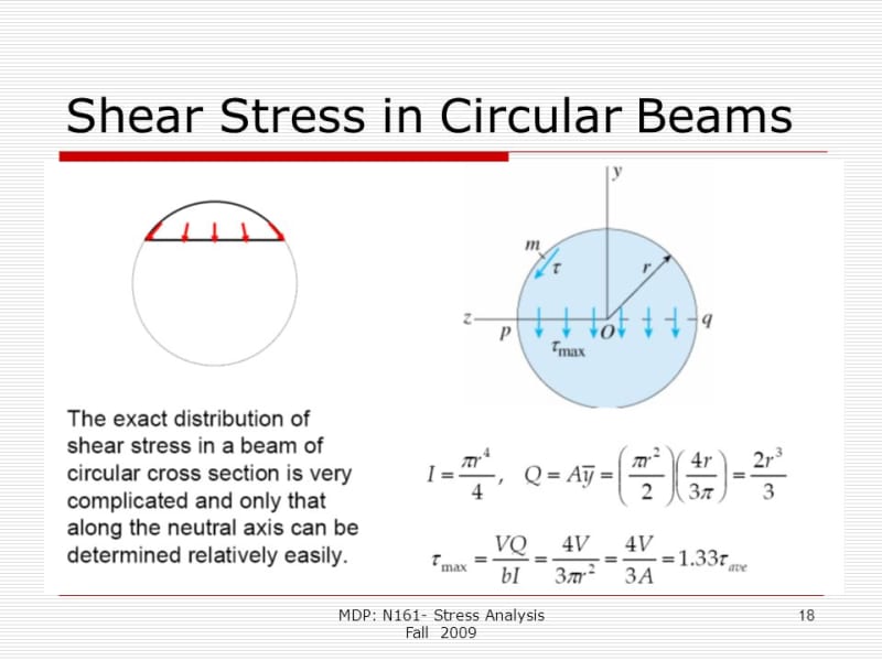
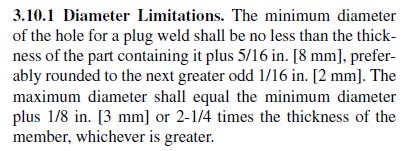
Can I get someone to point me in the right direction? Here is my problem. I have a driveshaft that is inserted into a square tube and than plug welded perpendicular to the axis. I was wondering if someone knew of a formula to help predict this(torque/stress)? Currently there is no documentation on our current process and I'd like to better document it for any future changes.
2022-05-24_14-14-41_vjsdcr.jpg
 
Replies continue below

Recommended for you

We don't know that each weld will share the load equally.

I say do the calculations for a single pair and if it shows sufficient strength then you're good to go.
 
I would go with a calculation similar to the following ;


slide_shear_stress_for_circular_upohjv.jpg

- Assume Electrode E70 , fexx= 21 ksi..⇒ τ all =14.85 ksi

- The max . shear stress for circular section τ max =4/3(τ aver) = VQ/(I*t)

- Allowable Resisting shear force for each spot weld Vall = 14.85 *(3/4)* (Π* r**2)ksi
( r= radius of weld area)

- Resisting Allowable torque Tres.= Vall* 2*R =14.85 *(3/4)* (Π* r**2)*2*R Kips-inch
( R= radius of shaft )

My opinion..
 
watch your units ! ... loads in ksi, torque in kips (smile)

I think i'd've let the shear be constant over the small area we're talking about ... 1.00 rather than the 0.75 factor, but meh.

another day in paradise, or is paradise one day closer ?
 
Is there any bending load on this shaft? If so, the plug welds will likely fail in fatigue.

If it's torque only, the methods proposed above seem like a good method.

Do you have any photos of a failed joint? If we know the failure mechanism we can design our analysis around that.
 
geesaman.d said:
Is there any bending load on this shaft? If so, the plug welds will likely fail in fatigue.

The OP indicates sprockets spaced along the length of sq. tube - no doubt there is bending load.

Proper analysis would indicate designing for bending ( evaluating shear flow for weld analysis) and torsion. I would avoid the design indicated by the OP. If there is insistence on the welded fabrication, I would prefer to install stubs with machined flats into each end of the square tube and fillet weld all around at the interface between tube and stub shafts, with secondary plug welds further in. Plug weld size based on AWS D1.1. The square tube should be designed based on fatigue with bending and torsion, and also a specified deflection and slope.

d1.1_ejj3xt.jpg
 
Scuka said:
Why? Plug welds are at the ends of the shaft, i.e. where the bearings are, i.e. where the bending moments are the smallest (in most cases almost negligible).

Only a stress calculation will show whether bending is insignificant. Your bending moment diagrams are appropriate only if the actual loads happen to match your assumptions. One overhung sprocket and bending becomes very important.
 
Status
Not open for further replies.
Back
Top