Continue to Site

Eng-Tips is the largest engineering community on the Internet

Intelligent Work Forums for Engineering Professionals

  • Congratulations KootK on being selected by the Eng-Tips community for having the most helpful posts in the forums last week. Way to Go!

Negative Slope Load Displacement Curve, Abaqus 1

Status
Not open for further replies.

Entherm

Civil/Environmental
Sep 23, 2020
34
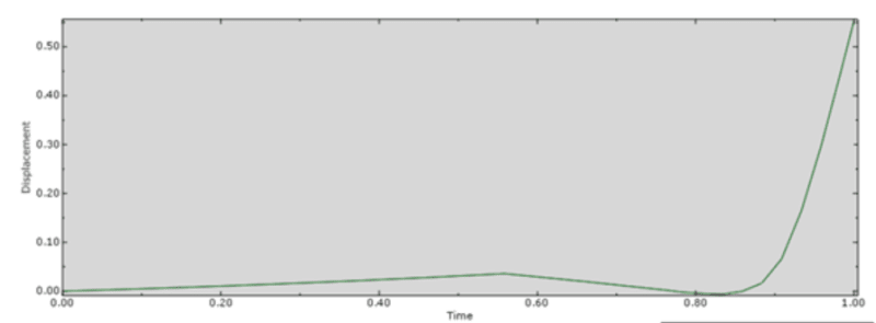
I am using steel with bilinear elastoplastic material. When I apply a compressive load on a beam (wire) element, After yield, I am getting a negative force-displacement curve for U3. What does that mean?
21-7_sfingu.png
 
Replies continue below

Recommended for you

This is displacement vs time plot. Could you also attach the force-displacement curve that you are talking about ?
 
Can you share a sketch showing your beam, boundary conditions and load applied to it and indicate degrees of freedom. Can you also share a deformed shape?
 
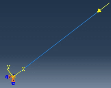
This is the beam; it is a simple steel rectangular beam with base fixed and static compression applied at the top. The beam would buckle at almost 1 kip but I have to apply a load beyond yield so I constrained (kinematic coupling) this beam with another beam (overlapped position) with a larger cross-section to increase the stiffness.
21-9_lesdyo.png

21-10_oe6ka5.png
 
Be careful with this unusual approach, it may cause some wrong or unexpected results as it seems in this case.
 
You mention that the beam would buckle at 1kip load, what are the units for force in your force-displacement diagram which peaks at 250 what? Have you tried to apply a prescribed displacement rather than the force?
 
The main beam is a very small rectangular steel section (1.5x2 in2), so the buckling load is very low, but if I couple it with another beam with a high capacity, it will stiffen the beam.
The units are in kips and inches.
 
Can you share the input file with us?
 
Having replied to your other thread I had assumed you were running a shell model. If you are truly interested in the buckling behaviour why not model the column using shell elements? For the beam element approach, have you tried running multiple cases with increased mesh subdivision?
 
Status
Not open for further replies.

Part and Inventory Search

Sponsor