Continue to Site

Eng-Tips is the largest engineering community on the Internet

Intelligent Work Forums for Engineering Professionals

  • Congratulations cowski on being selected by the Eng-Tips community for having the most helpful posts in the forums last week. Way to Go!

Negative (-ve) Buckling Factors 2

Status
Not open for further replies.

cad1009

Civil/Environmental
Jan 13, 2012
6
i have done an 4 Arch model on staad & performed buckling analysis.

i am getting very large -ve buckling factors .... what do they mean,
i know that buckling factor <1 means that member will buckle before the designed load,

the snap shot attached below is for Self weight. (Plz See the Pic attached)


Secondly how can i know the buckling factors of any other member of my choice .
 
 https://files.engineering.com/getfile.aspx?folder=2370d6a0-04c1-434f-93a6-32cbb48e62c6&file=Capture-3.JPG
Replies continue below

Recommended for you

A simple explanation can be that the buckling is based on a reversed loading. The governing case can be when Self weight is working up instead of down :).

Thomas
 
@ThomasH
self weight working up ??
i doubled checked that first thing when i got those -ve buckling factors .. :)
 
You might find this file helpful.

I've generally found negative eigenvalues when either my support conditions have been wrong, or I have very stiff plan bracing. The model is showing some numerical instability in some kind of way.

You want to look at the first sensible eigenvalue and plot the deformed shape. Whats actually buckling? How does it compare with your own hand-calculation? Remember Ncr(arch) = Axial Force in Arch(static case)*Eigenvalue. What effective length would this be equal to, by backcalculating Ncr = PI^2*EI/L^2 to get L? Does it look right? In the software I use (LUSAS) you typically specify buckling load rather than eigenvalue, maybe in SAP its different. Also try deleting the rest of the structure in a new model and only doing the analysis for the arch, applying a simple point load for the loads. These are the types of things you should always do when attempting a more novel analysis and somethings funny.

I noticed something in one of your other posts. "i know that buckling factor <1 means that member will buckle before the designed load" - yes, but it could also fail if greater > 1. Euler buckling theory is an upper-bound solution, it will give you an un-safe answer for the collapse load. You need to allow for imperfections e.g. Perry-Robertson buckling curves to get the "real" buckling load.

For the secondary elements I wouldn't bother with the buckling analysis and just design them simply based on Lcr = L etc

gl
 
 https://files.engineering.com/getfile.aspx?folder=3b95b70d-7d33-40b0-a5f1-9dcf07de6ebf&file=1030_Negative_Eigenvalues.pdf
@cad1009

What I mean is that the structure may have its lowest buckling load when the when the Self weight is working up (negative direction). It is not that you defined it wrong.

Check if the part that buckles is in tension for Self weight. A slender part in tension can be very sensitive to buckling in this case.

Thomas
 
Well ... Eigenvalue can be negative and positive ...as the solution of the mathematical equations
but only the positive one are of interest for engineers
forget the negative ones
most engineering software will automatically 'hide' the negative ones


As per ThomasH comments, the members that are reported as having negative buckling factors are probably in tension for the self-weight load case.
Obviously members seeing tension dont buckle, therefore the software is reporting these negative values, which means that if the value of the tension force is assumed as a compression force then this would be the buckling factor, i.e if the load was reversed (self-weight acting upwards).
Can you check that these members are in tension, if not then something strange would appear to be happening in Staad (P.S. I've never used Staad)
 
Yes ...the negative eigenvalues are correct....but of no interest for engineering ....
 
Negative buckling factors represent the buckling factor if the load used in the buckling analysis were reversed (multiplied by -1).
 
You could avoid all this by doing what I told you to do in the other thread. It's a couple hour operation (if that).

Trusting a buckling load from a FEA program is nuts. There are a million things you likely didn't include (like initial imperfections).
 
I see now that there are two treads discussing this question from differens aspects.

The buckling value or buckling load you get from this analysis can not be used for design, at least not directly. You can use it to calculate the buckling length for the members in the structure and then use those values together with material strengt etc to design using STAADs code check. Just ensure that you understand how the different parts of the design process shall wort together.

The buckling value is based on a perfect structure with infinite material strengt (Euler buckling). Like WARrose says, there is a lot of things it doesn't include.

Thomas
 
@ThomashH
totally agree, analysis results shown were only to verify that buckling is no goning to cause problems, Initial imperfection i cannot estimate at the moment, depends highly on section procured and fabricator engaged, that was reason i was worried about structural buckling limits for the given section profiles.
Further these arches need to be analyzed for construction sequences, all those things coupled led to this analysis so that i dont miss any thing...
i have used direct analysis for design.
 
cad1009

What you have done, if I understand it correct, is a linear buckling analysis. You have determined critical load,Pcr.

Pcr for a single member is Pcr=PI^2 * E*I /(Lcr^2). Lcr is critical length or buckling length.

Notice that in that formula the strength of the material is not included. The numbers you have shown so far does not show that buckling is not an issue. Since the numbers are fairly high it may very well be so but it requires more work to be sure. A buckling factor of 116.6 would imply less then 1% material utilization which would be either rubbish or bad engineering. I would have a look att the negative numbers just to ensure that there is nothing unexpected in the model.

Regardless of what software you use it is a tool to help you do your work. Just make sure that you understand how it works and the limitations in the method.

Thomas

 
@ThomasH agree, you cannot use the model by itself to conclude that the arch is not susceptible to buckling. Even though the eigenvalues appear to be quite high, you still need to account for second order effects or imperfections. This is typically done by using Perry-Robertson buckling curves to get the "real" buckling resistance - this is typically not done in the model but using design equations. The model will give an upper bound or unsafe estimate of the buckling load. I would still not be happy with the negative eigenvalues; try deleting the rest of the structure apart from the arch and see how your values pare up. I think you should add in the wind load as well for the buckling case, iirc the arch was significant out of plane.

I would not use STAADs code check to design the arch.

Once you're satisfied with Ncr by:

1)Deleting the rest of the model except the arch, and see if you still get negative eigenvalues.
2)Checking the buckling shape looks right.
3)Comparing your hand-calculate estimate
4)Again checking it looks roughly right (it will be probably be somewhere between L/3 and L/2).

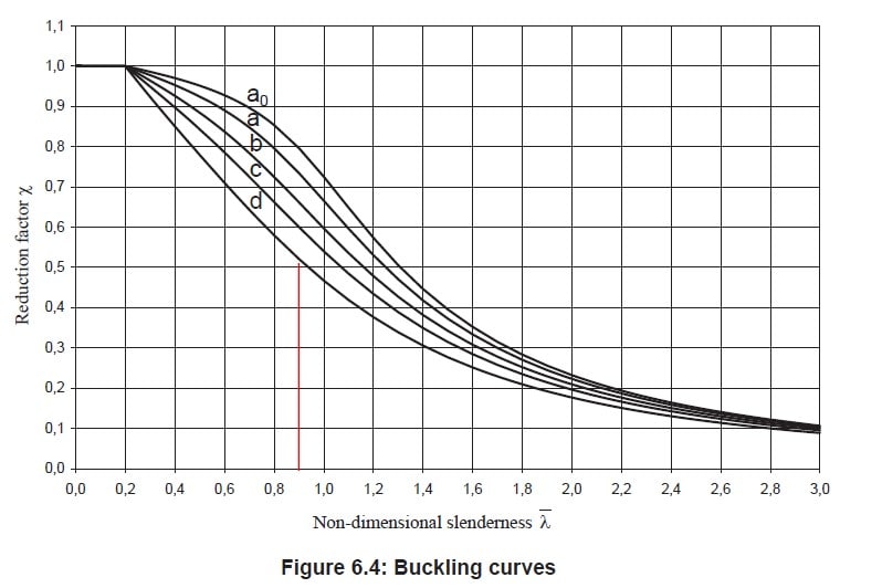
Get a book for your country's code and look at how to go about designing the arch. You will need to allow for imperfections etc using Perry-Robertson buckling curve. It will often look something like this (depending on your country) - the Ncr is the value you have calculated.

xsrmfKL_rrr6il.png

buckling_curves_g7htfw.jpg


Remember, it needs to allow for both axial force and bi-axial bending. Write it down on a piece of calc paper or make a simple spreadsheet.

gl hope the project works out
 
@ukbridge
@ThomasH
Thanks guys for your valueable advises, work isnt complete but things are shaping up, i checked buckling for main achres (without any internal members) & that resolved the -ve buckling factors. which was most likely due to tension in trusses & cross beams (still checking though).
attached is the pic below for buckling analysis results for main arches.

i know u guys r gona explode abt FOS, but i will optimize once i know exactly how the struc is responding to applied loadings. :)
 
 https://files.engineering.com/getfile.aspx?folder=10db7171-c3e7-41e7-943b-8c186fe74cae&file=Capture.PNG
I've said most of what needs to be said in my previous post however:

I don't see anything to do with FOS in that picture, all I see are eigenvalues. I've discussed this in great detail in my post above, do NOT use the eigenvalue alone to check for buckling(!). An eigenvalue is anything but a factor of safety, it doesnt account for combined bending/axial compression, it doesnt include second order effects etc. It doesnt even include the weight of the full roof either, or any wind loading (?). I think you didnt go far enough in your test model, you should really delete everything but the arch to make it as simple as possible. Remove the gravity load and use a simple point load as well.

For a buckling analysis you apply the full, factored ULS loading in a single loadcase. You then do an eigenvalue buckling analysis. To get Ncr its Axial Force in Arch * Eigenvalue or load factor. It doesnt stop there - you must account for second order effects using your code. You then check it for combined axial force and bending and shear using your code.

Also how does it compare to your hand-calculation? Use the document I gave you in the other thread.

You need some kind of mentor to help you with this.

I would probably abandon the buckling analysis and just use the equations given in the document I referred you to. Look at Ncr, and back-calculate the equivelant Lcr =sqrt(PI^2*EI/Ncr). It should be about 2L/3 - L/3. If not somethings probably not quite right and you've used a wrong number somewhere.

Get the coexisting moments/axial forces/shears in the arch for 3 different points. Check each point for combined bending, compression and torsion. Don't be afraid to design it for 80% etc, I would use a bigger wall thickness than you need, connections will come back to haunt you later.


PS Do not use the STAAD design facility, do it by hand!

Hope it works out, gl
 
@cad1009.

I don't think you understand what we are trying to tell you.

You need to ask a senior collegaue regarding you approch, and do it asap.

ukbridge advises you to not use STAAD:s code check and I can to some extent agree. But I don't think that is the problem here. My concern is if you use a code check at all? Euler buckling is not a design check, buckling factor is not a utilization or a FOS (Factor of safety) in relation to a code.

Like I said before, the software is a tool. You need to know the limitations in the software and in the methods you use.

Good Luck

Thomas
 
Status
Not open for further replies.

Part and Inventory Search

Sponsor