Continue to Site

Eng-Tips is the largest engineering community on the Internet

Intelligent Work Forums for Engineering Professionals

  • Congratulations cowski on being selected by the Eng-Tips community for having the most helpful posts in the forums last week. Way to Go!

Net-tension capability of parent material around cutout after doubler reinforcing repair.

Status
Not open for further replies.

spagett

Aerospace
Jan 18, 2021
4
Hi All,

I am a bit confused about the behavior of metal doubler reinforcing repairs for cutouts. Say I have a plate loaded in tension, the standard method of sizing the repair is to go 1 gauge thicker, and size the amount and type of fasteners / required doubler overlap needed based on the load capability removed as a result of the cutout.

For the sake of this conversation lets ignore the stiffness increase due to adding the doubler.

Doubler_p8kyqr.png


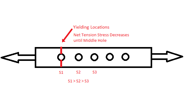
Without the reinforcement clearly the loadpath around the cutout is altered. Clearly the material above and below the cutout now has increased load.

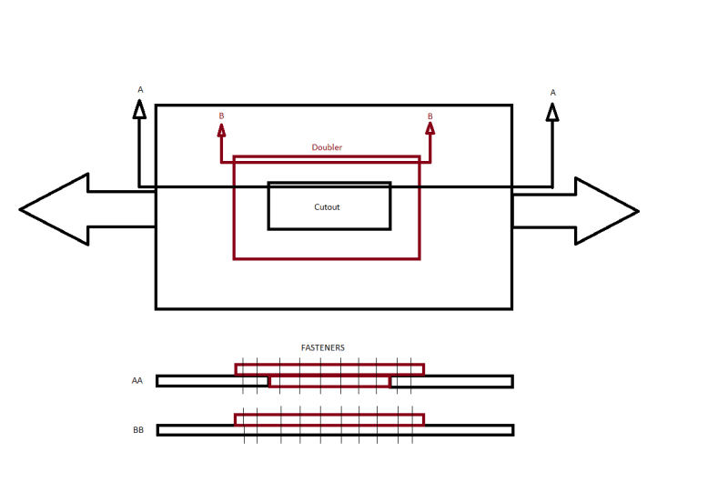
Once the doubler is applied does the loadpath around the cutout return to a relatively unaltered state, or is there still some degree of bypass around the cutout?

For section AA there is a clear loadpath from the parent material into the doubler, but in for section BB how much load transfer would actually be transferred into the doubler (assuming same material, but 1 gauge thicker). It seems to me like section BB is not really a joint. The doubler is there, but what is it actually doing?

So at section BB if there is still bypass around the cutout, and the load does not transfer well into doubler then we should have a big concern about net tension in the parent material.

The doubler approach is very clearly time tested and very clearly works. But my question is how are these repairs not failing in net tension?
 
Replies continue below

Recommended for you

You've rightly noted that the presence of the cutout introduces an in-plane bending moment in the ligaments on either side.
Not a big deal for small cutouts (e.g. antenna coax pass through), in which case I'd work to the limits of the relevant SRM, which will hopefully give you standard repairs as a guide (assuming you're in the mods/repairs domain, and not clean sheet design).
For larger cutouts these effects warrant explicit consideration - the net section through each ligament needs to be sized appropriately, and the skin-doubler joint needs to be able to conduct the portion if the moment carried by the doubler. For one exanple, see Niu's sizing of a bent around a cutout in a beam web. It's not a great example, but gives you an idea.
 
"how are these repairs not failing in net tension?" ... 'cause you're looking at only a very small portion of the problem. And because tension loads are usually dominated by fatigue allowables (so the tension stress in the original structure is low, so the structure can probably accept the cut-out without a doubler (but we'd never to that ... well, hardly ever).

You should look into compliance modelling of the doubler (Niu has an example). This allows us to appreciate the load transfer through the rivets into the skin.

You are correct, load has to go around the cut-out (obviously). For typical design I like the doubler width to be at least 3 times the cut-out width. Now I feel I have a good "story" for net section stresses. Then the load path into the dblr is the next important issue ... see compliance model for fastener forces.

BTW, your sketch isn't clear ... are you repairing some damage (so the cut-out is in only the original skin, or is the cut-out a thru hole (in both skin and dblr).

another day in paradise, or is paradise one day closer ?
 
For clarification the cutout is only in the original skin.

I did some 1D modeling of the BB cross section and it turns out the assumption there is poor load transfer into the doubler at that section is just plain wrong.

My other question would be how does the load transfer into the doubler change once the parent material begins to yield? Even though as previously mentioned the parent material would likely not reach yield stress, I would still like to know.

Parent Material of Section BB (please ignore different fastener count)

Doubler2_xhznar.png


The since the outermost fastener has the highest bypass load, that net area will begin to yield before the others. Is that localized yielding going to make the fastener at that area more effective in transferring load (less bypass) or less effective?
 
More typically, long before the onset of net section tensile yielding, you will exceed the bearing yield strength at many of the fastener holes, leading to redistribution of the load evenly hetween the fasteners.
 
please look at the compliance analysis in Niu.

"Net tension" almost doesn't exist in your real structure. Sure, at the two ends of the dblr there is some local net section, but this would yield and the load redistribute away. In the real world it'll never get near to yielding as tension stresses are limited by fatigue concerns.

Yes, dblrs are quite inefficient at attracting load from the skin, (in my experience the stress under the dblr is about 2/3 of the gross stress) but they're all we've got.
And they create a problem with the fuselage structure they attach to ... fatigue at the boundary load transfer fasteners, attracting load from surrounding structure (because of added stiffness). But the problem is manageable.

another day in paradise, or is paradise one day closer ?
 
Spagett…

Never forget that the devil is in the elements of: materials; cutout and doubler shapes; and crossing sub-structure [frames, stiffeners/longerons, intercostals, etc]; and fillers and fastening [with added holes], etc... especially for repairs and mods ['beef-ups', un-stiffening, etc]… or in conjunction with embedded access doors/windows or mounted parts [antennas, masts, etc]. My head hurts... simple examples can explode in real life.

BTW... the filler You added to the cutout in the skin... and fastened to the doubler... makes little sense to me... unless the filler bridges the missing skin [gap/thickness] to join with crossing substructure [not shown].

Regards, Wil Taylor
o Trust - But Verify!
o We believe to be true what we prefer to be true. [Unknown]
o For those who believe, no proof is required; for those who cannot believe, no proof is possible. [variation,Stuart Chase]
o Unfortunately, in science what You 'believe' is irrelevant. ["Orion", Homebuiltairplanes.com forum]
 
You don´t worry about the AA section but just the AA but just deal with the BB section where you have a hard point a a stress build up due to pin loading through the doubler. That is why you only analyze that section and estimate the loads at the doubler perimeter fasteners using Tom Swift or other method, all based on experimental studies.
 
well, that depends (on the ratio of the opening width to the dblr width). A big dblr with a small opening, then AA shouldn't be a problem (but often people crunch numbers to show that they can crunch numbers).

But the little known "dirty" secret is riveted dblrs are not very efficient at reducing the stress at a cut-out. The main thing they do is
1) improve the shear loadpath around the cut-out, and
2) complicate the inspection of the cut-out, and
3) provide a laminate to hide the rivet CSK in !

However I doubt we'd ever design a cut-out without a dblr. It'd just take too long to discuss it with everyone ad nauseum.

another day in paradise, or is paradise one day closer ?
 
Status
Not open for further replies.

Part and Inventory Search

Sponsor