Continue to Site

Eng-Tips is the largest engineering community on the Internet

Intelligent Work Forums for Engineering Professionals

  • Congratulations KootK on being selected by the Eng-Tips community for having the most helpful posts in the forums last week. Way to Go!

Network Balancing at Transmission level?

Status
Not open for further replies.

Msingh15

Electrical
Sep 14, 2020
8
Hi All,

My question arose when i had a look on switchyard of railway network. The railway network in WA (Western Australia) works at 25kV AC, the railway network is given 2 phase connection at 132kV level. My question is how is the 3rd phase balanced, since the rail draws significant load when running, how is the imbalanced encountered at transmission level?

Looking forward to the replies..
 
Replies continue below

Recommended for you

Usually the main transformer has an special connection to balance the single phase load among the three phases of the transmission network.

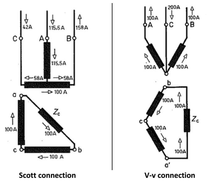
This connection is any of the 3 phase to 1 phase variants (Scott, LeBlanc, V-v,...).

This balance is not perfect, but is much better than just a single phase load. See below some examples (Zc being the load):

3-1_ofhign.jpg


With several transformers (connected between different phases) and some simultaneity of loads in large traction networks, the final balance is even better.

Hope it helps.
 
Hi Argotier,

Thanks for your reply. What i grasped from your answer is that the scott Tx connection is for 3 phase primary side connection and then 2 phase on secondary, correct me if i am wrong?

With the configuration we have here is, 2 phase connection, the transformer at railway swithchyard is 2 phase 132/25kV.

Thanks

 
Are you sure that they are not using single phase?
Two phase is possible but it may be physically challenging to arrange two overhead lines and two sets of pantographs.
Some electric railways use 25 kV single phase.
There are several connections that develop single phase from three phase without special transformers.
The most common are the zig-zag and the delta.
These connections do not require special transformers.
They are commonly used to convert smaller three phase generators to single phase generators.
For all three phase to single phase transformations, transformers or generators, there is a 1/3 loss in capacity.
Consider a transformer secondary connected in delta.
A single phase load across one side of the delta will cause equal current in all three windings.
The current in each winding will be 1/2 of the load current.
For a given load, assume 100 KVA for an example, 50 KVA will be developed in each winding.
The current will be the same in each winding.
the kW will equal the load kW.
A drawback is that for a unity power factor load, the current in one out of phase winding will be at 50% PF lagging and in the other out of phase winding the current will be at 50% PF leading.
The 50% PF in two windings is the reason that three times 50 KVA can equal 100 kW.
This is a common connection and numbers for a generator conversion to single phase.
I have no idea how WA does it.

Bill
--------------------
"Why not the best?"
Jimmy Carter
 
BTW in the V-v connection, this does not produce true two phase.
The phase displacement is 120 degrees while true two phase has a phase displacement of 90 degrees.
One of the phase angles of the V-v primary may be reversed. 120 degrees rather than the 60 degrees shown.
This will reduce the current on "C" phase primary line.

Bill
--------------------
"Why not the best?"
Jimmy Carter
 
My bad, I meant that the connections shown are 3 phase to single phase (now edited in the original reply).

These were only examples to show how the balance works with trx connections, an specific railway application may vary.

The particular railway trx connections I've seen always use in the secondary a single phase with mid-point (not quite a 2 phase system, although sometimes it's called that way wrongly), so you have two phases 180 degrees apart. For the V-v example its more like a V-v-v (the two secondaries "v" in phase opossition)

Your railway system probably is something like that, with a 25+25 kV network (this is very common).
 
You may call a 180 degree shift, two phase, but a two phase motor won't start on it.
When two phase motors were common they were wound for a 90 degree phase shift.

Bill
--------------------
"Why not the best?"
Jimmy Carter
 
Two phase requires at least 3 wires. Two wires is single phase. Even if those two wires are two phases of a three-phase (or even a two-phase) system.
 
This paper illustrates many of the transformer types used for track-side utility 3 phase to track circuit conversion. In all cases the track is wired for only single phase connection at the locomotive. If the load is not distributed reasonably, the resulting load at the utility connection will be unbalanced to various degrees. The exception is when a static var compensator is inserted to move load between phases.


Delivery of 3 phase traction power to the locomotive was tried, and except for very limited situations was discontinued.
 
Status
Not open for further replies.

Part and Inventory Search

Sponsor