RodRico
Automotive
- Apr 25, 2016
- 508
TL;DR... I've decided to abandon the gapless ring concept I was pursuing, because the I don't and likely won't ever know all the variables needed to assess its viability.
I came across an article from Wiseco describing thermal runaway in piston rings. While it doesn't say anything I didn't already know, reading it made me to realize I was assuming and modeling only expected normal cases. I have no idea how to quantify the unexpected abnormal cases and their severity short of an elaborate and costly set of experiments, so I decided to abandon the ringless concept. Instead, I will use a gapped ring with the traditional 0.003" gap per inch of bore rule of thumb which I now understand accommodates a host of unexpected and difficult to model conditions.
Though I plan to use a Dykes ring so my intake and exhaust ports close at the top of the piston face, I decided to first develop and validate a model for a standard pair of rings. The first task was to round up applicable data and I found two papers that met my needs: "Thermal Characterization of Combustion Chamber Deposits on the HCCI Engine Piston and Cylinder Head Using Instantaneous Temperature Measurements," and "Temperature Distribution of Piston Rings and Piston in High Speed Diesel Engine."
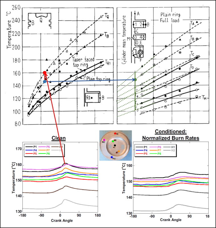
The bottom figure below from the first paper shows piston temperatures in an HCCI engine running at half load (max load in my engine) while the top two figures from the second paper show temperature distribution in and around the rings. I used the bowl temperature from the HCCI paper in the lower left figure to look up the temperature near the ring lands (B) in the upper left figure. I then used the ring land temperature from the upper left figure to look up temperatures of the rings in the upper right figure. Next, I applied the specified temperature for the cylinder wall water jacket and the inside radius of each ring then adjusted thermal resistance of each interface to replicate the temperatures of the paper.

Having established the thermal resistance of the contact surfaces, I applied convective heat using the average transfer coefficient and bulk gas temperature from my math models and observed results that did not correlate well to the papers. Assuming my math models were to blame, I reviewed them in detail and found them lacking; I had used a single average piston speed and time period for all phases of the cycle. While this method is appropriate and common for analysis of a crank driven engine, it does not account for the differences in piston speed and cycle time during the scavenge, compress, expand, and blowdown phases of the cycle in a cam driven engine. I corrected the shortcomings of my math model then plugged the new transfer coefficient (379 W/m^2/K) and bulk temperature (554K) into the model and observed results that correlate well with the papers. Not only do I now feel I have a good thermal model for FEA analysis, I now also have improved confidence in my corrected math model (on the plus side, it now shows slightly less heat loss and slightly better efficiency).

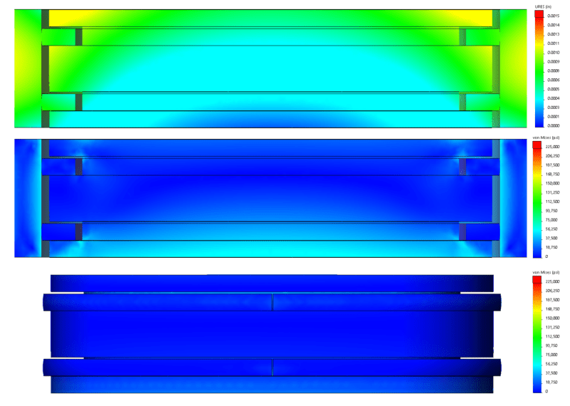
Moving on to FEA analysis, I first ran the normal case in which all surfaces are allowed to expand according to temperature. Combustion pressure of 3,600 psi is applied to all surfaces of the combustion chamber including those behind the top ring. I don't have a good figure from CFD for top ring leakage yet, so I set pressure on the second ring at 180 psi just to ensure it stayed in contact with the piston. Finally, I applied 15 lbf expansion force across the ring gap. The results are shown below. Note the very small expansion of all assemblies in the top plot resulting in the comparatively low temperatures associated with normal operation (recall I'm designing for Low Temperature Combustion with equivalency of 0.446 or 32.5:1 AFR). The middle plot shows a section view of stress with results less than one quarter the yield specification (300 kpsi @ 300C) of my chosen material (Maraging 350 steel). Note the pressure across the bottom face of the piston which results from it being held stationary in the vertical direction with 3,600 psi applied to the upper face. I set the ring gap to 0.003" per the traditional rule of thumb (0.003" per inch of bore, which now understand encompasses worst case thermal run-away conditions), and the bottom figure shows it has only closed 0.0014" in normal operating conditions.

Just for giggles, I ran another case of the model with the cylinder walls constrained to zero radial expansion. The results are shown below.

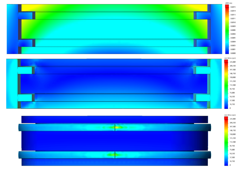
The top plot shows the constraint on the cylinder wall which yields zero radial expansion at the interface between the rings and the walls. The second plot shows stress on the rings has risen substantially over the normal case (note the whole cylinder wall is more stressed as well because its inside diameter is constrained). The bottom plot shows the ring gap has almost entirely closed, though some small gap remains.
My next steps are: 1) Incorporate the Dykes top ring; 2) Refine piston crown and ring land thickness to reduce piston height (every 0.25" of reduction in piston thickness yields 1" reduction in engine diameter); 3) Evaluate running CFD to refine pressure distribution and update math models to reflect the results; 4) Finalize experiment design; 5) Run critical experiments (fuel injector prototype, motoring model to evaluate cam stability while collecting data on FMEP and compression pressure).
It's a long road ahead. Sometimes I feel like everything is going too slow but then I remind myself new engine designs normally take a couple of years of effort by a significant design team equipped with fantastically expensive tools. I suppose mine might take a decade (not counting all the time I spend learning) and I've only consumed one or two thus far. Nonetheless, I often ask myself why I didn't just invent the next Scrub Daddy. That guy has made millions.

I came across an article from Wiseco describing thermal runaway in piston rings. While it doesn't say anything I didn't already know, reading it made me to realize I was assuming and modeling only expected normal cases. I have no idea how to quantify the unexpected abnormal cases and their severity short of an elaborate and costly set of experiments, so I decided to abandon the ringless concept. Instead, I will use a gapped ring with the traditional 0.003" gap per inch of bore rule of thumb which I now understand accommodates a host of unexpected and difficult to model conditions.
Wiseco said:"If the top ring is gapped too small, when it expands the ends will run into each other. As the engine heat-cycles back and forth through its maximal temperature, the top ring expands and contracts. If the gaps are too small, the top ring ends will run into itself. Since the ring has nowhere to expand at this point, the outward force applied to the cylinder increases. This added force introduces even more heat and the ring expands further. Once that happens, catastrophic failure will occur rapidly as it is a continuous cycle of more heat, more outward pressure, and nowhere for the ring to expand into.”
Though I plan to use a Dykes ring so my intake and exhaust ports close at the top of the piston face, I decided to first develop and validate a model for a standard pair of rings. The first task was to round up applicable data and I found two papers that met my needs: "Thermal Characterization of Combustion Chamber Deposits on the HCCI Engine Piston and Cylinder Head Using Instantaneous Temperature Measurements," and "Temperature Distribution of Piston Rings and Piston in High Speed Diesel Engine."
The bottom figure below from the first paper shows piston temperatures in an HCCI engine running at half load (max load in my engine) while the top two figures from the second paper show temperature distribution in and around the rings. I used the bowl temperature from the HCCI paper in the lower left figure to look up the temperature near the ring lands (B) in the upper left figure. I then used the ring land temperature from the upper left figure to look up temperatures of the rings in the upper right figure. Next, I applied the specified temperature for the cylinder wall water jacket and the inside radius of each ring then adjusted thermal resistance of each interface to replicate the temperatures of the paper.

Having established the thermal resistance of the contact surfaces, I applied convective heat using the average transfer coefficient and bulk gas temperature from my math models and observed results that did not correlate well to the papers. Assuming my math models were to blame, I reviewed them in detail and found them lacking; I had used a single average piston speed and time period for all phases of the cycle. While this method is appropriate and common for analysis of a crank driven engine, it does not account for the differences in piston speed and cycle time during the scavenge, compress, expand, and blowdown phases of the cycle in a cam driven engine. I corrected the shortcomings of my math model then plugged the new transfer coefficient (379 W/m^2/K) and bulk temperature (554K) into the model and observed results that correlate well with the papers. Not only do I now feel I have a good thermal model for FEA analysis, I now also have improved confidence in my corrected math model (on the plus side, it now shows slightly less heat loss and slightly better efficiency).

Moving on to FEA analysis, I first ran the normal case in which all surfaces are allowed to expand according to temperature. Combustion pressure of 3,600 psi is applied to all surfaces of the combustion chamber including those behind the top ring. I don't have a good figure from CFD for top ring leakage yet, so I set pressure on the second ring at 180 psi just to ensure it stayed in contact with the piston. Finally, I applied 15 lbf expansion force across the ring gap. The results are shown below. Note the very small expansion of all assemblies in the top plot resulting in the comparatively low temperatures associated with normal operation (recall I'm designing for Low Temperature Combustion with equivalency of 0.446 or 32.5:1 AFR). The middle plot shows a section view of stress with results less than one quarter the yield specification (300 kpsi @ 300C) of my chosen material (Maraging 350 steel). Note the pressure across the bottom face of the piston which results from it being held stationary in the vertical direction with 3,600 psi applied to the upper face. I set the ring gap to 0.003" per the traditional rule of thumb (0.003" per inch of bore, which now understand encompasses worst case thermal run-away conditions), and the bottom figure shows it has only closed 0.0014" in normal operating conditions.

Just for giggles, I ran another case of the model with the cylinder walls constrained to zero radial expansion. The results are shown below.

The top plot shows the constraint on the cylinder wall which yields zero radial expansion at the interface between the rings and the walls. The second plot shows stress on the rings has risen substantially over the normal case (note the whole cylinder wall is more stressed as well because its inside diameter is constrained). The bottom plot shows the ring gap has almost entirely closed, though some small gap remains.
My next steps are: 1) Incorporate the Dykes top ring; 2) Refine piston crown and ring land thickness to reduce piston height (every 0.25" of reduction in piston thickness yields 1" reduction in engine diameter); 3) Evaluate running CFD to refine pressure distribution and update math models to reflect the results; 4) Finalize experiment design; 5) Run critical experiments (fuel injector prototype, motoring model to evaluate cam stability while collecting data on FMEP and compression pressure).
It's a long road ahead. Sometimes I feel like everything is going too slow but then I remind myself new engine designs normally take a couple of years of effort by a significant design team equipped with fantastically expensive tools. I suppose mine might take a decade (not counting all the time I spend learning) and I've only consumed one or two thus far. Nonetheless, I often ask myself why I didn't just invent the next Scrub Daddy. That guy has made millions.

