Tscott8201
Electrical
- Jan 7, 2009
- 11
All,
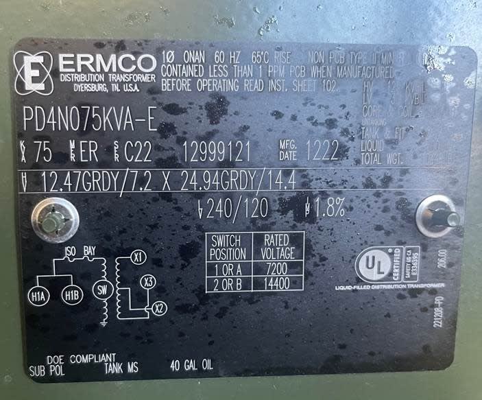
I'm having a weird result when trying to No load loss test a new batch of 75KVA 24.9/14.4x120/240 single phase pad mount transformers. These units are essentially a single bushing pole mount transformer in a box with with H1 being the primary connection and H2 being grounded to the case. When we perform a no load loss test (open circuit test) we are having this particular batch trip out the test equipment as if an internal short is present. Test connections are as follows.
Test equipment H1 lead to TX H1A lead
Test equipment H2 lead to TX Ground lug
Test equipment X1 lead to TX X1
Test equipment X2 Lead to TX X3
Test equipment applies a voltage to the X1 and X3 bushings and H1 and Ground are open with voltage being measured.
When these units are put in the test cage and energized via the H1 bushings, we measure 120/240 volts as expected and the units appear to operate as intended. The only instance in which we are having issues is the no load loss test. What could be causing the issue?
My running theory is that they are wound backwards (additive versus subtractive) causing the ground connected side of the primary winding to become energized instead of the H1 bushing when a secondary voltage is applied. I plan to test this theory today by swapping the test connections on the X1 and X3 bushings but I wanted put this up here to see if this theory holds water or if I am misunderstanding the transformer polarity concept.
Any help would be appreciated.
Thanks,
Tom