Eng-Tips is the largest engineering community on the Internet

Intelligent Work Forums for Engineering Professionals

NODAL FORCES - ENFO 2

Status
Not open for further replies.

Doodler3D

Mechanical
Jan 20, 2020
188
0
16
US
Hi,

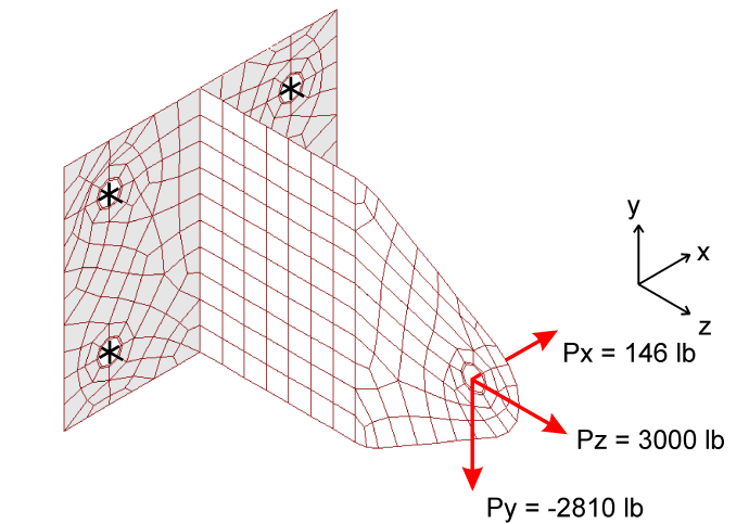
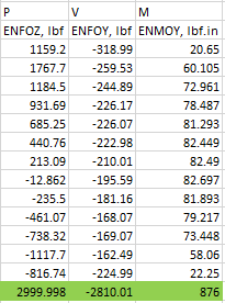
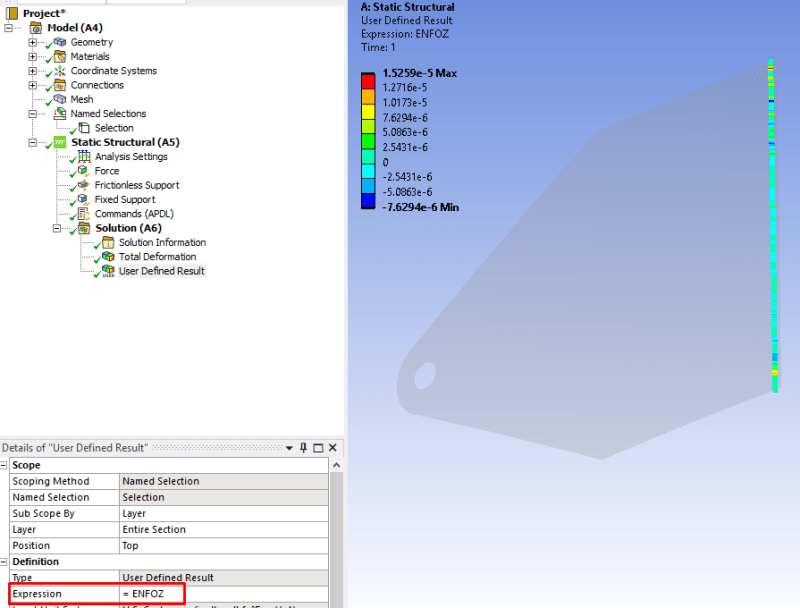
For unknown reasons, I cant get reasonable values of nodal forces for a scoped entity along the base of a weld. Any advise on the use of ENFO APDL command?

Thank you.

Screenshot_299_v4ixse.png
 
Replies continue below

Recommended for you

Hard to tell what could cause this. What kind of values do you expect? It's hard for us to give any real advice without knowing loading conditions, boundary conditions and coordinate systems used. A plot of nodal forces along a line without further information is not sufficient information.
 
@petb, for some unknown reason, the solver gave correct values with a glued contact defined at the intersection, but not with shared topology (one complete surface). I suppose it had something to do with the native step file export?
 
@Doodler3D Do you have activated Nodal Forces in Output Controls? Did you check your coordinate system in the user defined results? Are the dimensions and mechanical properties also correct?

Best regards
JK
 
Yes, I had activated the nodal forces in the output, as well as the co ordinate system was correct. I think I got it to work correctly.

Screenshot_302_dp8nay.png
 
@Doodler3D so possible reason is bad connection via shared topology? I observe this behaviour from time to time but it usually ends by rigid body motion not wrong results.

What is your final solution? Do you create a model from scratch or you do a glued connection?

Best regards
JK
 
Yes, I did a glued connection. I'm not sure what went wrong. I was able to replicate MA Weaver's method correctly. Thank you.
 
Try selecting only the elements on the part with the hole with the forces. If all the elements are selected, the reactions sum to zero, as your plot shows. Thats why it works for bonded contact and not shared topography. And dont forget SPOINT at the centroid of the weld group so your moments are accurate.

Rick Fischer
Principal Engineer
Argonne National Laboratory
 
@Doodler3D
Hello, so your origin question was to have separate parts, no share topology and to have contact (weld) between these parts. I see the point thanks to @rickfischer51

 
You can have shared topology, but you have to select the elements on the edge of one of the parts to be joined by the weld, and then select the nodes on that edge. Put a local CSYS at the origin of the weld group, and set the SPOINT as the global coordinates of the local CSYS. Set the RSYS to the local CSYS, then do FSUM,RSYS. The resulting reaction forces will be in the correct csys and the reaction moments will be around the centroid of the weld group.

Rick Fischer
Principal Engineer
Argonne National Laboratory
 
 https://files.engineering.com/getfile.aspx?folder=cd3269d4-a3cc-4ddd-b10d-ba9be2e55369&file=weld.JPG
@jkupka84 the default is to use shared topology/continuous mesh, and avoid the use of MPCs and contact, especially large models.

Rick, now its clear, define a local co-ordinate system while extracting unaveraged nodal forces for sizing welds.
 
Status
Not open for further replies.
Back
Top