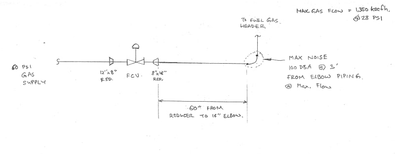
We have installed a flow control skid, and have measured noise at the downstream piping in excess of 100 DbA. We will likely be designing a similar installation in the future, and am looking for some input on how to mitigate noise in a gas piping system.
- See attached sketch.
- The skid is located inside a large open building, and 85 dBA max. noise limit is desirable for plant operations that may be working in the area.
- We've added acoustic insulation and cladding to the piping resulting in a reduction of about 5 Db.
- The header skid feeds fuel gas to several burners, the header will modulate various flows and pressures, but we design theoretical noise for a worst case max. flow condition.
- The Flow Control valve is sized by our valve supplier for a max. theoretical noise of 85 DbA at 3' from the valve. However, I believe what we are seeing is noise originating from the flow control valve propagating through the downstream piping, which results in a much higher value at the piping.
Some thoughts I've had:
1) Increasing the straight run of pipe after the pressure reducing skid before the 16" elbow. I'm unsure on how to come up with an estimate of length of this run.
2) Designing for a more gradual pipe bend/transition. Currently we have a 16" standard elbow, perhaps a series of 30 degree or 45 degree elbows?
3) Installing a silencer or conditioning plate downstream of the skid, I'd be curious if anyone has experience with such a device.
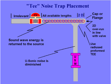
4) A noise "trap" (see attached image clip). I came across this in some literature from an ultrasonic meter supplier to mitigate noise upstream of the meter. I was pondering putting in a straight run of pipe with a dead-end, and then install a "T" takeoff which would go to the gas supply. I would likely acoustically insulate the straight run of pipe around the "trap"
Thanks in advance.
- See attached sketch.
- The skid is located inside a large open building, and 85 dBA max. noise limit is desirable for plant operations that may be working in the area.
- We've added acoustic insulation and cladding to the piping resulting in a reduction of about 5 Db.
- The header skid feeds fuel gas to several burners, the header will modulate various flows and pressures, but we design theoretical noise for a worst case max. flow condition.
- The Flow Control valve is sized by our valve supplier for a max. theoretical noise of 85 DbA at 3' from the valve. However, I believe what we are seeing is noise originating from the flow control valve propagating through the downstream piping, which results in a much higher value at the piping.
Some thoughts I've had:
1) Increasing the straight run of pipe after the pressure reducing skid before the 16" elbow. I'm unsure on how to come up with an estimate of length of this run.
2) Designing for a more gradual pipe bend/transition. Currently we have a 16" standard elbow, perhaps a series of 30 degree or 45 degree elbows?
3) Installing a silencer or conditioning plate downstream of the skid, I'd be curious if anyone has experience with such a device.
4) A noise "trap" (see attached image clip). I came across this in some literature from an ultrasonic meter supplier to mitigate noise upstream of the meter. I was pondering putting in a straight run of pipe with a dead-end, and then install a "T" takeoff which would go to the gas supply. I would likely acoustically insulate the straight run of pipe around the "trap"
Thanks in advance.