Continue to Site

Eng-Tips is the largest engineering community on the Internet

Intelligent Work Forums for Engineering Professionals

  • Congratulations KootK on being selected by the Eng-Tips community for having the most helpful posts in the forums last week. Way to Go!

Non-Linear Convergence

Status
Not open for further replies.

Nick7805

Mechanical
Nov 19, 2021
21
I'm trying to model a silo with a hopper (shell elements) resting against the ground (solid elements) using Inventor Nastran. In my current model, the ground has significantly lower stiffness than the hopper base and there is a separation contact defined between them. There is also various offset bonded contacts set between components of the silo, however the ground/base separation contact by-far produces the most contact elements.

I'm having a lot of trouble getting convergence, even at very low load levels (0.01% total load). I've attached a picture of the model below for reference.
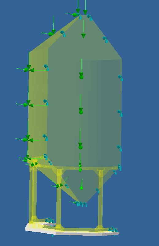
Capture_xtgbrs.png


The model will run and produce good results as long as the ground isn't in the model. Only when I add the ground to the model, I have issues getting convergence. So far I've tried the following:
- Reducing the number of contacts in the model (reducing the activation distance for base/ground contact)
- Modifying the convergence criteria to not include the load
- Modifying the convergence criteria to start at a low load level and increasing the number of increments
- Reducing contact stiffness to 0.5
- Changing the contact type from separation to separation with no sliding, as very little sliding is expected
- Testing as a bonded contact -- the model runs and produces results as expected if the contact is set to bonded

Typically the convergence issue is with load (and to a lesser extent, work); displacement always has converged so far. Depending on the settings, the solution either diverges or reaches the maximum number of bisections permitted. I'm fairly inexperienced using FEA and I'm not sure what to do in order to diagnose and fix the problem. Does anyone have any suggestions?
 
Replies continue below

Recommended for you

Dear Nick,
You need to stabilize your model, this is the primary action when solving contact problems, when the solver starts contact iterations the contact elements are not like springs, they don't have any stiffness, then is critical to stabilize your model to avoid to have a mechanism, ie, rigid body motions that produce a zero in the diagonal of the stiffness matrix.

Your solver will give you many options to stabilize your model: using soft springs (ie, add a very small values to all terms of the diagonal stiffness matrix), or mesh with a few CROD elements with very small stiffness in a few directions to stabilize your model.

Without the model in hand is difficult to know exactly the type of problem you are having and how to fix it exactly. Also, each solver has its own limitations, then is hard to know by advanced.
Best regards,
Blas.

~~~~~~~~~~~~~~~~~~~~~~
Blas Molero Hidalgo
Ingeniero Industrial
Director

IBERISA
48004 BILBAO (SPAIN)
WEB: Blog de FEMAP & NX Nastran:
 
In real life the silo must be somehow connected to the ground, right ? I don’t know much about these structures but I assume that they pretty much never stand freely on the ground and are fixed in some concrete base instead. Thus, you could approximate this connection in FEA to make the model more realistic and also less prone to convergence issues.
 
Thank you for the reply Blas and FEA.

@BlasMolero I have a parameter for contact stabalization set on in Inventor Nastran called "CONTACTSTAB". I'm unfortunately not able to post the model.

@FEA_Way It's not true that they are fixed to the ground, they really do often freely sit upon the ground. These silos are for agricultural use.
 
Hello!,
Sometimes we can consider the contact effect between tank and ground to define more accurate the bolts in the base.
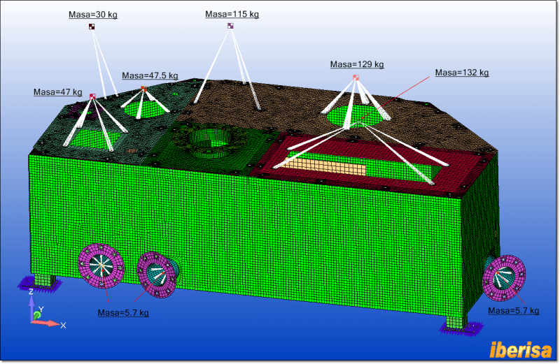
For instance, I remember a project I did years ago using FEMAP & Simcenter Nastran of a tank:

modelo_de_elementos_finitos_ewcc5v.png


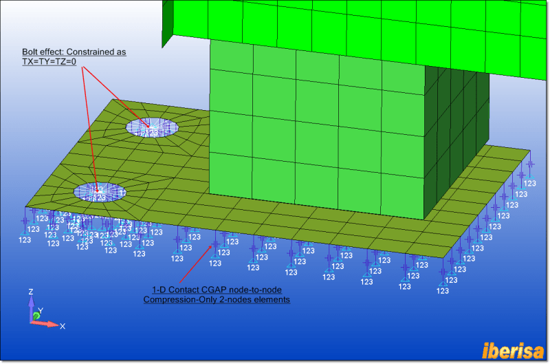
The unit was supported by four legs tied to the base using two bolts per leg of M10. The use of 2-nodes CGAP node-to-node contact compression-only elements neglect the penetration of the support plate in the floor, this is an elegant way to allow some legs of the tank (the portion of the support plate not working at compression) to rise by the action of lateral acceleration loads but neglect to go down. Today's I can use modern surface-to-surface contact, yes, but the use of CGAP node-to-node contact elements is a fast alternative as well, and the problem can be solved not only as linear static analysis (SOL101) but also with basic nonlinear module of Simcenter Nastran (SOL106):

detail_of_restraints_ulxm13.png


I post the pictures here to explain why sometimes we would be interested in considering contact effects between components & base floor.
When the floor is not infinitely rigid, then we need to extend the finite element model properly to mesh a portion of the floor ground as well, and include bolts contact, bolt preloading effect, etc..
Best regards,
Blas.

~~~~~~~~~~~~~~~~~~~~~~
Blas Molero Hidalgo
Ingeniero Industrial
Director

IBERISA
48004 BILBAO (SPAIN)
WEB: Blog de FEMAP & NX Nastran:
 
I am surprised you're seeing separation with the ground points ... maybe due to some side load ?

the model runs "well" with (I presume) rigid constraints for the ground ? Have you tried using finite stiffness constraints (3 rods) ?

Have you looked at the displaced shape with the ground ? I imagine that the perimeter of the ground is fully constrained ? and the depth of the ground is appropriate (I have no idea) ?

another day in paradise, or is paradise one day closer ?
 
@BlasMolero, thank you for your detailed reply. I will look more into using gap elements; I know it's possible in Inventor Nastran, however so far I've been unable to find info on how to assign them. From what I understand, you can assign a stiffness for gap elements?

@rb1957 yes there is a wind load that causes lifting. I don't want to use a finite stiffness constraint in this case because of the lifting. I've looked at the displaced shape of the ground and it seems like my contact is working fine if it is set to bonded.

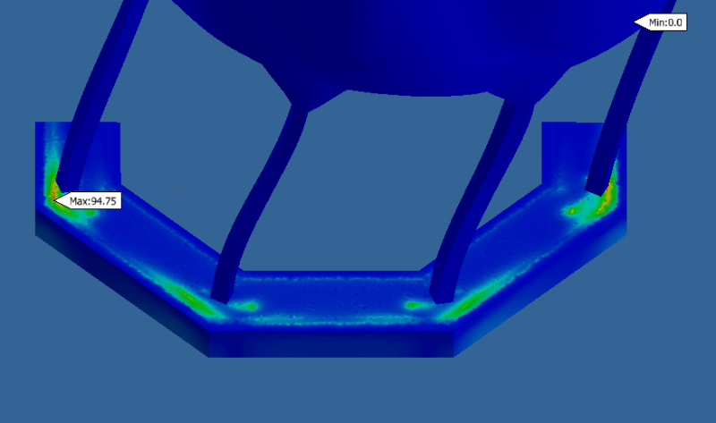
@IceBreakerSours, I ran a normal modes analysis and I'm obtaining frequencies between about 7Hz and 23Hz. This is almost no change from the frequencies I obtained before the ground was added. I can also see the contact appears to be working as intended. Is there any other info I could obtain from this analysis? I've posted a picture of the stress gradient in the ground for mode 1.

Capture_p8qlka.png
 
still don't believe you need a contact element with the ground. Your structure should be well attached to the ground, a bolt can carry tension. Now whether the ground around the footing fails is a different question ... and one which should IMIO (In My Ignorant Opinion) size the footing. But yes a gap element has a defined stiffness until the gap opens. Attached in an excerpt from the element manual ...

What is limiting the size of the "ground" ? It looks like there is lots of green lighting up the edge of your modelled ground ?

another day in paradise, or is paradise one day closer ?
 
 https://files.engineering.com/getfile.aspx?folder=11c5adff-9881-4ce9-bea1-0aeace99d077&file=gap_element.pdf
@rb1957 as I mentioned to FEA_Way, these structures are left unanchored more frequently than they're anchored. Because of that, I'm not using bolts in the analysis.

Before I answer, what do you mean by the limiting size? And are you referring to the gradient up the sides and the bottom of the ground -- would this indicate the ground is perhaps not thick enough?
 
ok, I'm surprised !

looking at your pic, there is a lot of green along the edges of the "ground". what's defining this edge? can the ground be wider ?

another day in paradise, or is paradise one day closer ?
 
@rb1957, yes I can make the ground as wide as I want. The only limitation is the number of nodes it adds to the analysis. Do you think this could be hindering convergence? I'll make it wider and run another simulation.
 
Here are some tricks that may help when the structure is standing freely on the ground and force control is used (depending on the capabilities of your software and on the assumptions that you can make):
- high enough friction coefficient
- automatic stabilization (artificial damping) for contact or for the whole analysis
- no separation contact, sometimes even sticky (cohesive) contact
- initial displacement control to establish contact
- discrete soft springs or dashpots
- automatic strain-free adjustment of slave surface nodes (check whether your software supports it), small initial overclosure might be a good idea when the adjustment option is available
- the use of symmetry (here you already did that but maybe your model could be reduced to even smaller piece of the entire structure)
- running dynamic quasi-static analysis

Theoretically, you could also go straight for tied/bonded contact and the analysis will converge without any troubles but this approach is often too far from real-life behavior (of course still better than ignoring the ground and simply fixing the base of the silo).
 
A few random thoughts:
- If you don't have lifting in the supports for any load situation you won't need contact elements since there is no separation beetween ground and support.
- If the possibility for separation is required, try gap elements. Then you can use a high stiffness for compression and a low for tension.
- If you run an analysis with self weight only, will that converge?
- Since you have convergence issues even for a very low load levels I suspect that the convergence issues are not load related but instead that the model is unstable. As BlasMolero already suggested, use springs to stabilize or use a dynamic approach as FEA_Way suggested. Either you remove the possible singularities (with springs) or you use a solution method that allows them (dynamic).

Also, if you have convergence with one criteria, why don't you accept that solution? Is there something wrong with that solution? You mentioned is the last paragraph of the first post that the convergence issues were only present for some criterias.

You work with Inventor Nastran which is the solver that used to be known as NEiNastran. There used to be a specific handbook for that solver with suggestions regarding nonlinear analysis. If you Google "Autodesk Nastran 2020 Nonlinear Analysis Handbook" I think you could find some help. At least I could find the Handbook that way and it has been updated with the Autodesk Nastran label.

Good Luck

Thomas
 
Thank you for all your suggestions everyone. I'm applying what I can to my model and learning a lot reading about these different things. Unfortunately, I'm not able to apply the quasi-static analysis, as Autodesk Nastran won't allow edge-to-surface contact types in dynamic analyses.

In regards to model stability, Nastran has a grid point singularity table. In that table, I do have a lot of singularities, but they're ALL nodes involved in the base/ground surfaces. Using the contact stabalization parameter(CONTACTSTAB), I believe the problem is fixed. However, I'm not 100% sure... as far as I've found, I'm unable to check where stabalization occurs.

@ThomasH, I'm wondering, how could I connect the solid ground elements to the base's shell elements without a contact? Inventor Nastran has very limited mesh control; all their solutions for connecting shell/solid elements either involve . I'm looking into gap elements as yourself and @BlasMolero suggested... I know they exist in Inventor Nastran, but I can't find out how to create them. They could maybe be the perfect solution.

Thank you again for all the help everyone, this is a great community!
 
"how could I connect the solid ground elements to the base's shell elements without a contact?" ... use a common node. You have two meshes (one for the ground, one for the structure) and presumably a gap element between two nodes. Either ...
1) if zero length GAP (so that the structure node and the corresponding ground node are in the same position), then overwrite one node (so that one node is in both meshes), or
2) embed the structure node into the ground mesh.

another day in paradise, or is paradise one day closer ?
 
Dear Nick,
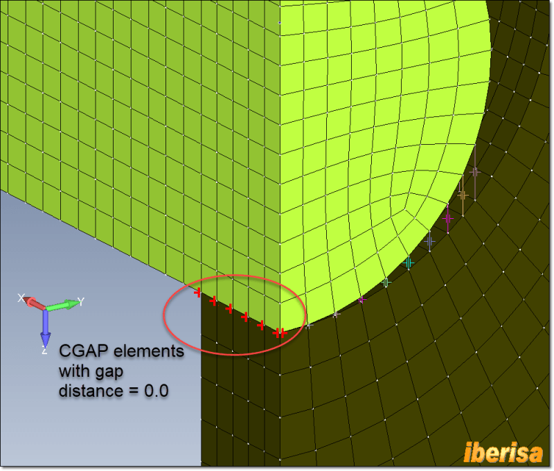
Before trying to solve real life problems you need to create pilot studies using simple models with relative low size to understand how to use the technology.
For instance, here you have an example of HERTZ contact using 1-D CGAP node-to-node contact elements:
CGAP12_dc3vok.png


Best regards,
Blas.

~~~~~~~~~~~~~~~~~~~~~~
Blas Molero Hidalgo
Ingeniero Industrial
Director

IBERISA
48004 BILBAO (SPAIN)
WEB: Blog de FEMAP & NX Nastran:
 
In addition to rb1957's answer, I think welded contact can be an option for the setup. Then you can "weld" two not similar meshes together. I know it is available in Autodesk Nastran, but I don't know how the Inventor interface is set up.

But my first question would rather be, do you need contact? If you have lifting in one of the supporting legs, couldn't that indicate a stability issue with the structure?

My impression is that you are drowning in complex boundary conditions. I suggest, take a step back and simplify until the model is stable, then consider what you actually need to include in the model. Personally, I can't really see a need to include contact in this analysis but I don't know the full extent of the problem. Or exactly what you are trying to achieve [smile].

Thomas

 
@rb1957
Autodesk Inventor has no simple way to allow that level of control, but I could do so by manually writing and adding cards into the bulk data file. There's also no easy way to to determine which nodes belong to a single face in a complex model, but I think I could figure out how to do that.

@ThomasH
There is lifting because of the loading, not instability. There is a horizontal load to represent wind. Hence the need for either contact or something like gap elements that will achieve a similar result. This is why I can't just simply used a bonded contact.
 
you can't add a point to the ground, like at the foot of the structure ?

I know Inventor stress package ... I personally don't trust it, I think it is too "hobbled" by getting it to fit simple mechanical design situations.

but You don't Really need a gap element. run with a positive connection, if you get a negative (not allowed) reaction, remove the constraint. you may end up with several simple runs. You could also determine the result (to a close approximation) with a hand calc ...
1) wind creates a moment about the base,
2) the moment is reacted by a "bending field" ... linearly varying reaction loads,
3) compare these reactions with gravity,
4) if bending > gravity then the support is lifting, and go back to 2) ... I suspect that when one support lifts the structure is close to falling over.
5) of course there are other failure modes (like bending + gravity > ground allowable).

another day in paradise, or is paradise one day closer ?
 
Status
Not open for further replies.

Part and Inventory Search

Sponsor