Dear Sir/Madam,
I am modelling a system which contains a hinge. The hinge angle is related to the applied torque according to a hysteresis cycle, something like: Torque=k1*Angle+k2, where k1 and k2 are constants.
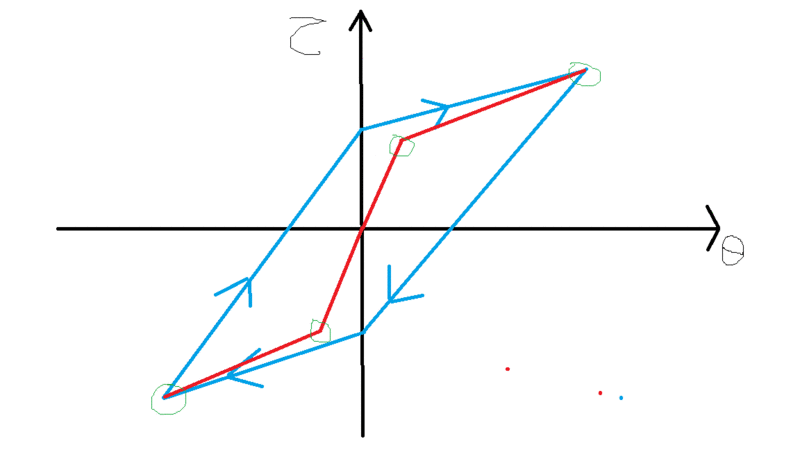
In particular, the torque vs angle relationship is as shown in blue in the figure attached. (Vertical axis = Torque, Horizontal axis = Angle).

I have modelled the hinge using a CBUSH element. In the PBUSH entry, I can define a stiffness constant K for the relevant rotational degree of freedom, but that would not be enough to model my hinge, since the torque vs angle relationship is more complex (see attached figure).
My first idea was to use the PBUSHT entry, and define explicitly the torque vs angle relationship in a table. I did it by drawing the red line of the attached figure, and defining in the table the points circled in green. Note that in reality I defined the green points as closer to the blue line, but they are shown further away in the attached figure just for visual clarity.
I applied an increasing imposed displacement using SOL 106, and the solution converges giving as a result the deformed structure. Since the displacement only increases from 0.0 to a certain value, the red line approximation should give an adequate result. There are no displacements in the opposite direction afterwards, or anything that would require modelling the unloading phase of the hysteresis cycle.
When I check in the f06 file the torque acting on the hinge, I find a small value of torque. If I consider the red line of the attached figure, for that torque value, the angle should be very close to 0. However, when I see the displacements, the angle is actually very large.
It is as if the solver is not following the torque vs deflection relationship defined in the table.
Do you have an idea of what could be happening? Have any of you modelled a similar system in the past?
Thank you very much in advance for your replies.
Kind regards,
Alberto.
I am modelling a system which contains a hinge. The hinge angle is related to the applied torque according to a hysteresis cycle, something like: Torque=k1*Angle+k2, where k1 and k2 are constants.
In particular, the torque vs angle relationship is as shown in blue in the figure attached. (Vertical axis = Torque, Horizontal axis = Angle).

I have modelled the hinge using a CBUSH element. In the PBUSH entry, I can define a stiffness constant K for the relevant rotational degree of freedom, but that would not be enough to model my hinge, since the torque vs angle relationship is more complex (see attached figure).
My first idea was to use the PBUSHT entry, and define explicitly the torque vs angle relationship in a table. I did it by drawing the red line of the attached figure, and defining in the table the points circled in green. Note that in reality I defined the green points as closer to the blue line, but they are shown further away in the attached figure just for visual clarity.
I applied an increasing imposed displacement using SOL 106, and the solution converges giving as a result the deformed structure. Since the displacement only increases from 0.0 to a certain value, the red line approximation should give an adequate result. There are no displacements in the opposite direction afterwards, or anything that would require modelling the unloading phase of the hysteresis cycle.
When I check in the f06 file the torque acting on the hinge, I find a small value of torque. If I consider the red line of the attached figure, for that torque value, the angle should be very close to 0. However, when I see the displacements, the angle is actually very large.
It is as if the solver is not following the torque vs deflection relationship defined in the table.
Do you have an idea of what could be happening? Have any of you modelled a similar system in the past?
Thank you very much in advance for your replies.
Kind regards,
Alberto.
