Eng-Tips is the largest engineering community on the Internet

Intelligent Work Forums for Engineering Professionals

Non magnetic rails

Status
Not open for further replies.

drodrig

Mechanical
Mar 28, 2013
260
0
0
DE
Hi there,

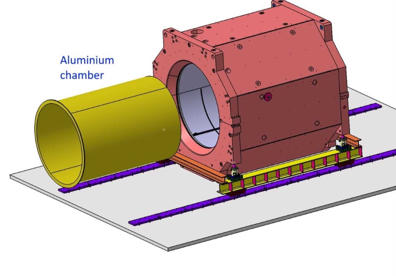
We need to insert an aluminium chamber (around 2 meters - 6.5 feet in diameter) into a magnet. It is 3 tons. Room temperature, clean environment. The total length to move is 8 meters -26 feet)

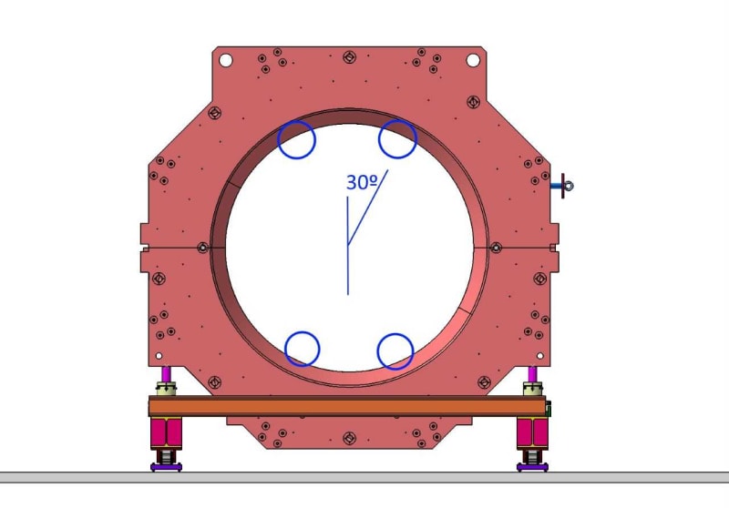
The idea is using rails. There will be some holders at +/- 30º (vertically).

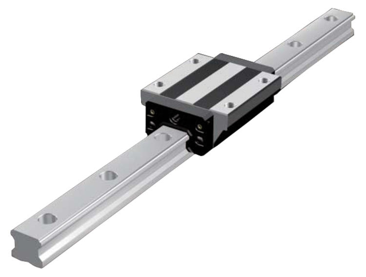
The rails can't be bigger than 25 mm/1 inch.

I was thinking to use precision linear. They can easily take the weight, they can slide the chamber accurately.

The problem is that these rails must be non-magnetic. I talked to many companies and they don't offer anything non-magnetic (austenitic stainless steel). I found some made out of aluminium but they can't take the load.

I can't believe there is a standard solution for this. We are starting to thing to prepare two surfaces on both the magnet and chamber and slide with PTFE in between.

Does anybody know any supplier providing non magnetic rails?

thanks
regards,
 
Replies continue below

Recommended for you

Here a couple of pictures:

001_majwkx.jpg


15_gllwbk.jpg


14_sgdai4.jpg
 
Does this need to be an off-the-shelf solution? A rail is a simple enough fabrication. Look at a lathe bed for an example. Good rails don't require complicated features.
 
I'd recommend HDPE rather than PTFE. PTFE is so soft it tends to gouge. The sliding friction is low but the gouging can turn it into a shear load in the PTFE, leaving loose fragments.

HPDE is about 90% as slippery as PTFE, but is far far more gouge resistant and it is difficult to create loose fragments.

Do the rails remain in the installation? What holds the aluminum tube in position?

It's not clear what supports the aluminum tube during installation before it is inserted into the magnet.

Finally - this question seems familiar - was it asked before?
 
I worked on one similar 30 years ago and we used cold drawn Nitronic 40 (or 50) for the rails.
Properties of 140ksi UTS and 120ksi Yield are available and it is very non-magnetic.

= = = = = = = = = = = = = = = = = = = =
P.E. Metallurgy, consulting work welcomed
 
Drodrig:
There is enough unsaid in you problem description to fill a fairly good sized book. 6.5' dia. and 26' longitudinal travel of the alum. chamber, in a straight line, from outside the magnet to its final position inside the magnet, seems understandable. But, which moves, the magnet or the alum. chamber? What are the dims. (thickness, length, i.d and o.d., otherwise it’s a perfect cylinder) of the alum. chamber and how is it supported during the various phases of the operation? How does it deflect under this support system? What’s the i.d. and length of the magnet? It looks like the magnet may move longitudinally on the blue rails, and if so, you support the alum. chamber on the inside with a “Y” shaped deep beam, 28'+ long and move the magnet over/around it. Your rails only have to be longitudinal guides then, more or less. But, you say max. size is 1", and do you mean 1" space btwn. o.d. of alum. chamber and the i.d. of the magnet? Make the “Y” shaped deep beam out of laid up fiberglass, supported at each end by small support frames. That’s 6000lbs. over 10' of a 28' long “Y” shaped beam. How close to the magnet can you get with steel structure and support on the outside?

If the alum. cylinder moves into the magnet, then you need an outside support rail system (steel?), under the alum. chamber, to line things up so you can start pulling/pushing the cylinder into the magnet, kinda like your first picture shows things standing. My bot. rails, the loaded rails, would be .5" thk. x 6 or 8" wide by 26' long alum. bar stock. They would be shaped to match the i.d. and o.d. and the inside would be lined with thin sheet PTFE epoxied/bonded to the alum. rails. There would be a least four load shoes on the alum. chamber which would slid on the longer load rails. How does the alum. cylinder deflect under these conditions? And, your two top rails are still just guide rails. Then, how do you get those rails out of the magnet, when the alum. cylinder is in place? Can the rails and load shoes stay in place? You might go back to my first scheme and put the “Y” shaped beam on end frames on rollers, which would allow the alum. chamber to be moved longitudinally along four guide rails inside the magnet.
 
Thank you all for the answers

I learnt earlier today that we can't use plastic or grease. These parts will be in a high radiation area for years, so they would be destroyed.

This now excludes the solutions with PTFE, HDPE, lathe rails...

Air bearings could be an option, but all the components to bring the air in must be stainless steel

The NSK link is for bearings. I called them. They said they can make the rails for us. But it is not standard; which means long delivery times and they won't be cheap. I gave all the information, let's see what they come up with.

Yes, you might have seen this magnet over here before. I asked about other components before.

About the Nitronic: I couldn't find any rails; does one need to design and manufacture them?

There will be a temporary aluminium profile structure with additional rails (aligned with the ones -permanent- inside the magnet)
 
We bought the Nitronic as cold rolled (rect) bar and machined rails.
I know that you can also get cold drawn rounds.

= = = = = = = = = = = = = = = = = = = =
P.E. Metallurgy, consulting work welcomed
 
A bunch of options.
In one case we used a high strength bronze, there are a bunch of Cu alloys that might work.
You could also just make them out of Nitronic as well, it doesn't like galling to itself.
Or a high strength Ni alloy.
It really depends on the other constraints.

= = = = = = = = = = = = = = = = = = = =
P.E. Metallurgy, consulting work welcomed
 
Yes, that shape but with air as the bearing fluid.
But when at rest they are touching so how the metals react to each other is important.


= = = = = = = = = = = = = = = = = = = =
P.E. Metallurgy, consulting work welcomed
 
OK - similar answer to before - set it up on its end and lower the part into place from above. Then there is no sliding friction.

Is this an open reactor core? The main degradation of Polyethylene under gamma radiation is that it cross-links and becomes harder, more abrasion resistant, and a bit more brittle and loses fatigue strength - but your application doesn't require any flexure so fatigue strength doesn't matter.
 
But you had a high air pressure to lift the block/skater on the rails? otherwise metal on metal won't be easy to move

3DDave, I don't understand what you mean.

It is a magnet in a particle accelerator. We need to simulate the radiation doses and check what material can take it. There is high current so it doesn't look good for plastic

cheers,
 
Ever seen them assemble the stages of a rocket? Or a tower? Set the open end facing up and lower the aluminum part into it.

In a particle accelerator there will be very little radiation off to the sides of the item. What does high current have to do with an insulator?
 
Status
Not open for further replies.
Back
Top