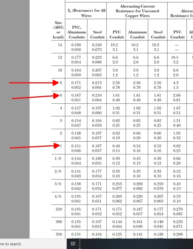
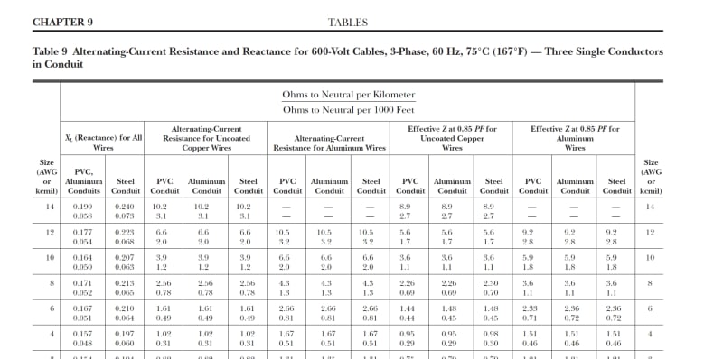
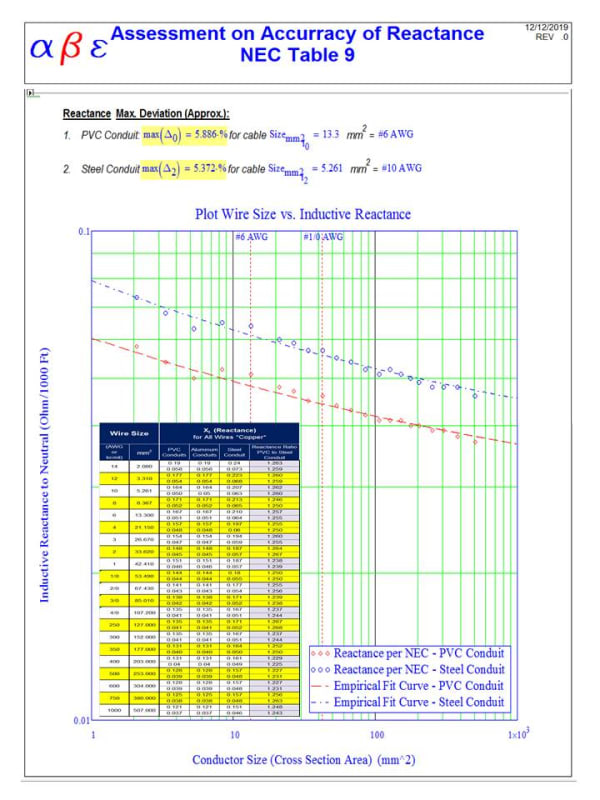
As we said earlier, the data on Table 9 for reactance, AC resistance, and effective Impedance at 85% PF, is accurate enough for most practical applications.
As a general comment, we should remember that the AC resistance is larger than DC resistance because of the skin effect. DC data it is not recommended to be used for accurate calculations in AC systems.
The reactance, on the other hand, depends upon the cable dimension (metallic conductor, Insulation & jacket) and the conductor arrangement in the raceway due to the natural random lay. This can only can be estimated by assumption.
It should be noted that the 600 V cables listed in table 9 there is a combination of 7 insulation thickness (15-70 mils) and 6 jackets thickness (4-9 mils) that definitely will impact the lineality of cable reactance data. That's why I do suspect the values were determined based on an actual test of typical rather than calculation.
In summary, I do believe that for practical purposes, the data in the NEC table 9 is accurate enough for most AC LV calculations
![[pc1]](/data/assets/smilies/pc1.gif "[pc1] [pc1]")
![[3eyes]](/data/assets/smilies/3eyes.gif "[3eyes] [3eyes]")
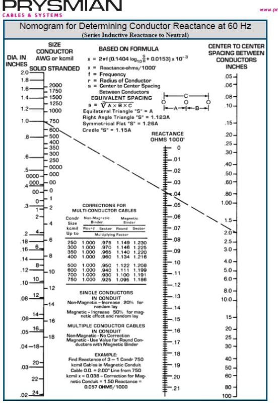
") Validated somewhat by this, but you are better:
Validated somewhat by this, but you are better: