Continue to Site

Eng-Tips is the largest engineering community on the Internet

Intelligent Work Forums for Engineering Professionals

  • Congratulations KootK on being selected by the Eng-Tips community for having the most helpful posts in the forums last week. Way to Go!

Nonlinear Large Displacement Analysis Returning Smaller Displacements than Linear

Status
Not open for further replies.

xp1

Structural
Feb 24, 2015
25
I was wondering if anybody else has encountered this, or if my results seem valid. I'm designing a canopy lift, basically a long HSS tube that's going to be picked up and moved. In SAP2000 I modeled the tube and the cables that will be lifting it; for the cables I modeled wire rope as a steel rod with the actual area and a reduced MOE value. I ran a nonlinear load case and the displacements were slightly smaller than the linear static case, which I would not have expected, although the analysis did converge so it seems to be correct. Any ideas why this might happen?
 
Replies continue below

Recommended for you

My belief is that Cables are always stiffer in transverse loading during a geometrically non-linear analysis than they would be in a linear analysis.

Think of it as a reverse P-Delta effect. The tension in the member has a way of reducing the lateral deflection of the cable.

Now, how that translates to your overall structure is not intuitive to me. But, I imagine it is related.
 
Your results may be correct.
With large displacement analysis a structure can go into catenary action, thus the structure tries to resist the applied loading by in-plane tension rather than bending.
The tension that develops increases the stiffness and hence deflections can be smaller.

Are you trying to account for large displacement of the HSS tube? What is the size of the tube and the distance between the supporting cables?
 
Thank you both for the responses. I think we've accepted that this is okay, it's a simple model.

Patswfc, we're not` worried about the tube displacement; it's an HSS20x12x.375 welded to an HSS12x12.375, 108' long with max distance between cables something like 27' and it's only deflecting 2.5" total at the ends compared to the middle so this seems okay.

My concern was actually that, we're using two ropes to pick up the tube at 4 places as you can see in the picture - the red are the actual ropes that will be used - but we're modeling the ropes as four separate elements and so I wasn't sure if we could trust this to determine the lengths of all the ropes/spreader bar. The tension in the bottom four ropes will be the same in real life so I wasn't sure if adjusting the geometry to make this happen in the model would be accurate.
 
 http://files.engineering.com/getfile.aspx?folder=c506de5d-af40-4272-8717-3164c478a705&file=SAP_Tube_Lift.PNG
I'm going to express a slightly dissenting opinion here. I believe that the only thing causing caternary effects in the cables of this system is the dead weight of the cables themselves. And that shouldn't add up to much of anything. My alternate hypothesis follows.

With the linear static analysis, everything is run on the undeformed geometry. With the non-linear analysis, the geometry of the system will change through the load history. The important consequence of that will be that all of your cables will be more vertical than they were at the start. And the cables being more vertical will lead to lower cable stresses and less cable elongation. These effects will be somewhat offset by the additional displacement of the cable ends resulting from rigid body cable rotation. Which effect dominates depends on the initial angle of your cables and how stiff the cables are.

xp1 said:
I modeled wire rope as a steel rod with the actual area and a reduced MOE value

Why reduce the modulus of elasticity? If anything , I would think that you'd want to reduce the the Ix/Iy values to reflect minimal felxural stiffness in the cables.

xp1 said:
but we're modeling the ropes as four separate elements and so I wasn't sure if we could trust this to determine the lengths of all the ropes/spreader bar. The tension in the bottom four ropes will be the same in real life so I wasn't sure if adjusting the geometry to make this happen in the model would be accurate.

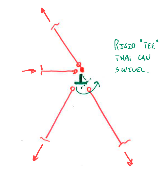
That is an interesting problem. Short of getting fancy with Abaqus or Adina, I'm not sure how one would best model the situation. Below, I've proposed a rigid swivel thing that might capture the fundamental aspects of the behavior. I haven't tried this myself so take it with a grain of salt.

Capture_gmkgzz.png


I like to debate structural engineering theory -- a lot. If I challenge you on something, know that I'm doing so because I respect your opinion enough to either change it or adopt it.
 
We reduced the MOE to account for the stretch the new cables will experience, does that make sense? And we figured they wouldn't take much moment anyways since they're so thin.

Hm so with that Tee, we'd want to make it remain in that position to ensure equal loading?
 
I don't really follow the sketch, but when a truss with compression members deflects and the diagonals become less vertical they take more load and deflect more. I'm thinking maybe the opposite is happening, as the truss deflects the cables become more vertical and effectively stiffer.
 
xp1 said:
We reduced the MOE to account for the stretch the new cables will experience, does that make sense?

It makes sense if you are referring to cable relaxation.

xp1 said:
Hm so with that Tee, we'd want to make it remain in that position to ensure equal loading?

Quite the opposite. The tee would need to rotate to simulate the cable sliding over a pulley of sorts.

I like to debate structural engineering theory -- a lot. If I challenge you on something, know that I'm doing so because I respect your opinion enough to either change it or adopt it.
 
KootK said:
It makes sense if you are referring to cable relaxation.

Yes I believe so - the first time these cables are used, they unwind a bit and therefore stretch greater than a steel rod of the same properties would, correct?

KootK said:
Quite the opposite. The tee would need to rotate to simulate the cable sliding over a pulley of sorts.

Ah yes, I was thinking I would let it rotate, but then try to get it not to - but that's not it because although the forces in the cables should be equal, they're at different angles so the T will rotate. Right?
 
xr1 said:
Yes I believe so - the first time these cables are used, they unwind a bit and therefore stretch greater than a steel rod of the same properties would, correct?

That's my understanding as well.

xp1 said:
Ah yes, I was thinking I would let it rotate, but then try to get it not to - but that's not it because although the forces in the cables should be equal, they're at different angles so the T will rotate. Right?

My thinking was that the cable will start off being of equal length on each side of the joint but, due to deflection of the HSS some of the cable will slide over the joint to the outside. My hope was that the TEE rotation could capture some of that. Like I said, though, it's just an idea. I'm not sure that it will produce the desired results.


I like to debate structural engineering theory -- a lot. If I challenge you on something, know that I'm doing so because I respect your opinion enough to either change it or adopt it.
 
This isn't as simple as it looks, because the cable moving over the pulley makes a big difference, but for a vertical lift it can be simplified fairly easily:

It is symmetrical, so you can model half the system.

The spreader bar means that you know the horizontal position of the two lower pulleys, so you can calculate the angle of the cable at each lifting point for any given cable length. The bending deflections of the item being lifted will be much greater than the axial deflections of the cables and the spreader beam, so they can both be treated as constant length (for the cable its the overall length that is constant of course).

You know the vertical load on each half of the system, so you can calculate the tension in each leg of the cables, and hence the vertical and horizontal loads at each lifter.

You know the tube has zero moment and shear at the end, so it is a simple hand calculation to find shear forces, bending moments, slopes and deflections along the beam to the centre line.

If your software has the facility to set up "string groups" you can also use those to do the calculation automatically or as a check. I know that Strand7 can do this, but I don't know what other packages will.

Doug Jenkins
Interactive Design Services
 
IDS said:
The bending deflections of the item being lifted will be much greater than the axial deflections of the cables

I don't agree with this; the bending deflections of the tube are going to cause axial deflections in the cables, and I don't think they can be neglected.
 
xp1 - The simplified method I suggested takes account of the movement of the cable around the pulley.

The only things it ignores are the increase in overall length of the cables and 2nd order effects in the tube. It would be quite easy to set up an iterative analysis on a spreadsheet to account for these, but the first will be very small unless you have rubber lifting slings. The magnitude of the 2nd order effects will depend on the stiffness of the tube, but standard buckling checks would be applicable since you know the first order axial load and bending moments.

Doug Jenkins
Interactive Design Services
 
Status
Not open for further replies.

Part and Inventory Search

Sponsor