Continue to Site

Eng-Tips is the largest engineering community on the Internet

Intelligent Work Forums for Engineering Professionals

  • Congratulations KootK on being selected by the Eng-Tips community for having the most helpful posts in the forums last week. Way to Go!

Noob Question Re: Woodchipper 1

Status
Not open for further replies.

moteor

Aerospace
Jul 17, 2015
2
Hi everyone,

Thanks for the help in advance.

I have a project with a woodchipper to deisel engine build, with a woodchipper that is rated to 105 HP @ 540 RPM. I was wondering what the torque rating for the machine would be, whilst its being driven from a diesel engine?

I believe there is a direct relationship between Torque and Horspower from Engines;
TORQUE = HP x 5252 ÷ RPM​

Therefore Torque = 1021 lb.ft or 1384.29 Nm

1) So I have done the math, but is that right? Is that really what the torque the machine can handle?

I also have the torque and HP stats of the engine as below:
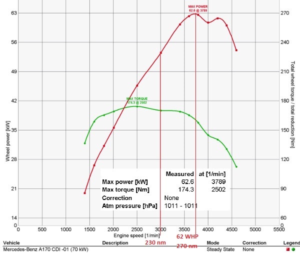
mercedes_spec_vuvi4a.jpg


I need to find the torque of the engine related by the rated torque capacity of the wood chipper = 1384.29 Nm. @540 RPM?

Also I need to find out what engine speed can provide the max torque rating for the machine as the engine has to be reduced by a ratio through pulleys to match the max RPM of the machine. My first question is:

2) Does reducing a gear ratio, say 3.7 : 1 multiply the torque by that much? So what would happen to the machine?

If;

Torque x gear ratio = torque at the wheel

Then @ 2000 RPM the engine would provide 169.1 Nm , therefore multiply by the 3.7037 times the motor is rotating faster than 540 RPM and you have the figure 625.92 which is under the figure we have for the rated capacity of the wood chipper.


3) At the moment I am working with this:

My plan is to have a compound pulley system with 3 groove vbelt pulleys rated to at least +20% over 105 HP.

I am looking at the 2 pulley sizes of 117.5 and 305.5 and being in a drive chain to have 2 of each.

they give a ratio of 2.6 : 1 so 2 of them is 2.6 x 2.6 = 6.76.

so at 3,650 RPM it will be reduced by 6.76 times giving 539.4 rpm. So this gives peak power at peak revs.

Please can you confirm if this is right or REALLY IS ALL IN MY HEAD!! :confused:
 
Replies continue below

Recommended for you

Most pulley ratings are based on torque. I'd take that max torque and plug it in at the maximum operating speed (conservative, since torque falls off at high engine speed) and use belt design software to handle the rest. Gates has a reasonably good software available.

1.2 seems like a low service factor - a woodchipper strikes me (pun intended) as having very high dynamic factors. I use 1.5 SF minimum for industrial fluid handling machines, for reference. Unless you intend for the belts to slip during overload, I'd go over 2.0.

David
 
moteor,

A horsepower is defined as 550ft.lb/sec. Your torque equation is probably based on this. You really ought to be able to work this out from first principles.

A crude rule of thumb is that your power is constant as it passes through your drive. If your wood-chipper is rated at 105HP at 540rev/min, that is what you should run it at. Your diesel engine must not exceed 105HP. Your drive must convert your motor's output speed to 540rev/min. Belt drives, chain drives and small spur gear reductions are approximately 100%[ ]efficient. In reality, you will get something less than your 105hp at the wood-chipper, which will help your safety factor a bit.

--
JHG
 
No one else going to ask why someone is trying to convert a Mercedes into a wood chipper?
 
V-belts are a bit different than gears since they can slip a bit if overloaded. In either case you would design your drivetrain to handle some worst case torque condition, such as the chipper section getting jammed. This condition would usually require having some type of torque limiting mechanism in the drivetrain, and you would use the release torque of this device as the max torque in your design.

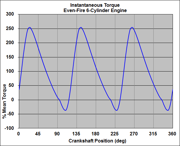
With regards to the torque produced at the PTO of the recip diesel engine, there will be peak instantaneous torques over the course of a single crank rotation that exceed the mean torque value shown above. The difference in these peak-to-mean torque values depend on factors such as inertia of the moving engine parts, number of cylinders, firing frequency, cycle pressures, etc. If you have a gear drive rigidly coupled to the engine, the gear teeth will be subject to the peak instantaneous torques. So you need to size your gearbox by applying the appropriate service factor for the particular engine configuration being used.
 
thanks for all the good info,

@Geesmand - I had a look for some design software on gates but couldn't find and, but have downloaded some and found some online too. I think you are right and doubling the service factor for safety to over 200% would be a good idea.

@Drawoh - I agree completely with everything you say. I was hoping to have the engine running at the RPM for maximum HP ~ approx 95HP

@3dDave - Cos am gonna!! Seriously though I am doing it to save costs, as a timberwolf of the same size is £20,000. So far on my build I am £3,000 all in.

@tbuenla - I was thinking to keep the clutch to act as a smooth power transference device between the engine and the drive train, so it can take up power slowly as the clutch engages. So in the event the chipper is jammed, the power can be released from the clutch, and also the safety drive disconnect on the chipper itself. As a general rule, what would you say the peak in the rotation for the torque would be as a percentage ? a guess is fine lol or maybe some science?

Thanks for all the help, and as nobody has pointed out my bad maths - does that mean I have worked it out correctly? I am not sure . . .

Thanks!
 
moteor-

Here is a graph illustrating the difference between instantaneous torque and mean torque you might see at the PTO of a recip piston engine.

ET-X-6%20Cyl.gif
 
I think MB A 170s use 4 cylinder engines, so the instantaneous torque variations may be even more severe than tbuelna's image.

Isn't that the model Benz that flunked the "elk test" even worse (actually capsizing) than some recent model Jeep ?
Was roll over damage why it was your cheap source for a prime mover?

Engine crankshafts are generally not intended to handle large continuous lateral loads, like a high power belt drive, so the driver puulley/sheave will need to be on its own jackshaft.
 
I assume 540 is the design speed for the chipper? Hopefully the max speed is higher because the engine you are using is an on-road model and the governor will probably not have as steep a characteristic as a stationary (constant speed) engine. So if you set the thottle to run at 4,200 rpm with no load (zero power) the governor will not apply maximum fuelling until the engine is loaded down to significantly lower revs (hopefully around 3,700 where the engine is making maximum power). You will have about 75 kw or 100 hp max available at the chipper which sounds ideal. (I added some kW to convert the "wheel power" to flywheel power). No need to worry about torque for ratio selection. Power does not get multiplied through gearing.

So if you gear it to run the chipper at 540 rpm at 3,700 engine rpm (6.85:1 reduction), the chipper will be doing 612 rpm at 4,200 engine rpm. If that is overspeed for the chipper you will have to increase the reduction ratio.

Forget about cyclic torque variation. That is what the flywheel is for. The small cyclic speed variation remaining with the big diesel flywheel will be absorbed by the belt drive you are proposing. The torque seen by the chipper will be relatively constant - the biggest variation will occur when a log goes into the chipper and that is what the manufacturer has designed it to do. I imagine the chipper has significant rotational inertia because those spikes in torque at the chipper blades are best absorbed there rather than overloading your belt drive by trying to slow down the diesel engine and flywheel.

je suis charlie
 
Forgot to mention. You need to check the high idle speed of your diesel (wide open throttle & zero load). From your graph it will probably be about 4,800 - 5,000 rpm). The gearing you choose must not overspeed the chipper at high idle. If this does not allow the gearing you want, you will have to modify the governor to reduce the high idle sped.

je suis charlie
 
Took a look at some existing designs of wood chippers with similar horsepower. They all used hydraulic drives. This would seem to make sense, as it would permit the chipper section and diesel engine to each operate at optimum speed, and would also allow a significant amount of slip in the drive due to variations in load produced at the chipper section.

The hydraulic drive also makes it easy to incorporate the powered roller feed system required for larger machines.
 
Wood chippers involve relatively significant rotational inertia in addition to shock loads. I would want to include a torque converter at the engine flywheel to temper the effects of acceleration to running speed and instantaneous torque variations from both the engine and the wood chipper. Including an overrunning clutch would be helpful to deal with the substantial coast-down issues at the end of operation periods. A suitable hydrostatic drive for feed rollers may work nicely, but all-mechanical drives with proper clutches have served well in many designs. Costs, configuration, availability, fabrication, and whatever other considerations will control what eventually makes the most sense for your situation.

Valuable advice from a professor many years ago: First, design for graceful failure. Everything we build will eventually fail, so we must strive to avoid injuries or secondary damage when that failure occurs. Only then can practicality and economics be properly considered.
 
Status
Not open for further replies.

Part and Inventory Search

Sponsor