Eng-Tips is the largest engineering community on the Internet

Intelligent Work Forums for Engineering Professionals

  • Congratulations waross on being selected by the Tek-Tips community for having the most helpful posts in the forums last week. Way to Go!

Normal stresses in torsion problem? 2

Status
Not open for further replies.

ajm4zc

Industrial
Oct 3, 2018
2
0
0
US
How do normal stresses arise in a "pure" torsion problem?

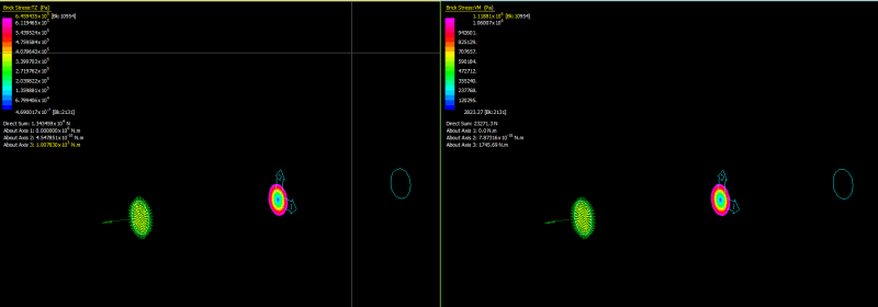
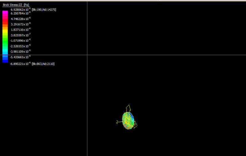
Example problem is 12" long solid shaft of 1" OD. One end is fixed, the other has a moment on the face of 500 lbin. Part was discretized in 3D using 2nd order trias. The resulting shear stresses match up fine with the simple hand calculations, but I am perplexed that there is a von-mises stress, and that it is about twice the max shear stress. How are normal stresses created in this shaft if they are not specified by the initial boundary conditions? Do is it have something to do with the elements used for meshing? How can I solve for these normal stresses by hand for this case?

Thank you.
 
Replies continue below

Recommended for you

Take a look at this post:
There are 3 potential causes:
- von Mises is not just a sum of stresses and when there is only shear component von Mises will still modify it according to the well-known formula instead of just giving the pure value of shear stress
- if you look at stresses at the fixed end they will be affected by that constraint and may have incorrect values
- fixing the bar in all degrees of freedom )m(including axial direction) may create additional stresses
 
As mentioned above VM is exactly that for pure shear.

Example (D=0.2 m, L= 2 m, Torque=1000 Nm, Steel, fixed on one end)

Theory: 6.37E5 Pa, and as can be seen from the left image below the TZ ("torque shear") is 6.46E5 Pa which is very close (sum om internal forces there give the exact applied moment also ~ 1007 Nm) so it is all good.
Finally VM (right image) is as expected about sqrt(3)*shear torque value, thus 1.12E6 Pa.

Capture_xbav8x.png


Now there might be some axial stress due to the applied loads and restraints (local effects though), but at the centre length (along shaft), the axial stresses should be almost zero in this case, since any local effects do not influence that area as it is locate 1 m away from restraints and applied moment.
Below is a slice of elements just at the the centre of the shaft, and as can be seen the axial stress (along global Z axis) is almost zero.

Capture2_hlskt8.png
 
Wow thank you for the quick and great responses. I'm happy I can solve this by hand now, next is wrapping my head around it all. I'll do some more reading and practice problems.

Thanks again guys.
 
VM equations are usually solved using the principal stresses, but the result of the equations is also known as "octahedral shear stress". Another way to think of it - under pure hydrostatic pressure, there are no shear stresses, all of the principal stresses are equal, and the VM calculation equals zero.

see the part that talks about "Hydrostatic and deviatoric components"
 
To add a bit of clarity, the *entire idea* behind VM is that it predicts failure due to shearing action (shape change).

The approach is to split the general stress tensor into a hydrostatic tensor and a deviatoric tensor and then disregard the effect from the hydrostatic tensor (the theory being that a material under a very large hydrostatic stress will not fail). This leaves only the deviatoric tensor (the shearing tensor) and the VM equation is based upon just this tensor. From a physical standpoint, this explains why the result is as stated in post #3. Note that this result is similar to the Tresca failure theory (shear failure theory) for a pure shear stress.
 
Status
Not open for further replies.
Back
Top