Continue to Site

Eng-Tips is the largest engineering community on the Internet

Intelligent Work Forums for Engineering Professionals

  • Congratulations SSS148 on being selected by the Eng-Tips community for having the most helpful posts in the forums last week. Way to Go!

Not using GD&T? 10

Status
Not open for further replies.

ctopher

Mechanical
Jan 9, 2003
17,505
My last company, and current, have argued with me about using GD&T.
Engineers, purchasing, and managers have argued that it makes the parts more $$.
I tell them no it doesn't.
Last company had parts machined in China, current in Thailand and in USA.
China and Thailand have said not to use it because they don't understand it.
Often I see parts made that don't meet print with GD&T, but are bought off anyway.
I'm at wits end, tired of arguing with everyone.
I also find more people here in USA that don't understand it.
Anyone here run into this? If so, what do you do?

Chris, CSWP
SolidWorks '20
ctophers home
SolidWorks Legion
 
Replies continue below

Recommended for you

Yes. We need at least one case study to support a marketing claim. There should be thousands of them by now.

You write much, say little. Experience is what allows for a nuanced opinion rather than one that sounds as if from a cult. You sound as if you have little experience more than memorizing a book.
 
Then I'm still waiting for your explanation of why you do not demand a case study from FEA software developers, same as you require the developers of the dimensioning and tolerancing standard to do.

Until you provide a rational explanation for that, your opinion is biased rather than nuanced.

You sound like someone who knows little more than how to point a finger at others.
 
I have seen case studies from FEA developers; I worked with one engineer who was a developer for the P-element software that was eventually sold to PTC.**

Demand answered. Now post your company name and the product you designed with representative drawings.

A moment on Google will turn up thousands of FEA papers; guess what "GD&T" turns up. The majority are advertisements for training, sometimes baited with simple examples.

A favorite/terrifying bait was one from Don Day who was promoting a profile tolerance control for a bracket to follow the curve of a pulley to keep the cable in the groove. Anyone who has dealt with that problem knows that is a terrible idea and that it is misalignment between the pulley and the rest of the cable path that causes the cable to climb. If that's not dealt with it progresses to chew up the side of the pulley and wear out the cable. Once the escape is in progress that bracket will either wedge the cable, become just another sacrificial part for wear, or cause enough excess wear to part the cable.

His concern was looking at fitting the bracket as a part without caring about the assembly or performance requirements.

** In the FEA market the H-element developers were there first and the refinement problem in H-element analysis that P-element was intended to overcome was overcome by the H-element developers adding more automation and better/more sophisticated adaptive mesh generators. This would have been a bad concept earlier, but RAM and CPUs were becoming so cheap and fast that typical FEA users didn't notice enough to want to change.

Often the stress engineers also perform a parallel hand calculation of major elements as verification that the problem is correctly modeled.

For PTC the P-element solver was worth it because the mesher doesn't have to be sophisticated and the user doesn't need to supply any initial hints; however it is also less flexible, particularly in the results interface, which the H-element people had been developing for far longer and for a much larger number of users.
 
Demand was not answered.
I asked you clearly why don't you require FEA software developers to present a case study to prove the advantages of performing an FEA over not performing one, just as you require the Y14.5 committee to publish a case study to support implementation of standardized dimensioning and tolerancing compared to a drawing that doesn't follow any standards.
Saying you "have seen case studies from FEA developers" is not enough, and is nothing at all. If it's about comparing different software programs and meshes it is irrelevant. I could point you to a paper that was published in an ASME journal, studying different geometric documentation strategies all involving "GD&T" callouts, and their effect on the downstream process, but that is not the type of thing you require, is it?

I googled FEA and the results are full of commercial content, just like for anything else. I converted poorly defined drawings to ones that utilize concepts and symbology covered by Y14.5 and saw the positive outcomes. I care little about what turns up on google about it. If you have the opposite experience to back up your approach, why don't you tell about that case when you redefined a drawing to eliminate any form control feature control frames such as flatness, replaced orientation geometric tolerances such as perpendicularity and angularity by directly toleranced angles and title block angular tolerances, deleted the datum feature symbols, removed any locational controls such as position and profile and replaced them by directly toleranced location dimensions etc. Go on and tell how this improved the performance of the product, reduced risks, benefitted the manufacturing and inspection and led to cost savings.

Usually Tec-Ease examples show an erroneous or ambiguous tolerancing scheme and provide an alternative definition method that makes for a rigorous specification, without going into detail about the tolerance values. These values should be driven by assembly and performance considerations. The datum selection is also driven by the assembly, and it is often shown.
Since you felt the need to pass a judgement on the example by Don Day, you should have done it meaningfully. I expect you to provide a link to the example, and explain how exactly his "terrible idea" to use a profile control on that feature is inferior to the original tolerancing scheme that probably didn't have that control. You should tell how the scheme he proposed takes less consideration of assembly and functionality requirements than the original design documentation. Tell how the original controls which he proposed to change do better at preventing the potential failure you describe. Until you do that, your criticism is unreliable.
 
Your concern over FEA is a distractive line of BS. You can point to an ASME document - you cannot point to one that details costs, the topic of this thread. Stay on topic.

"I converted poorly defined drawings to ones that utilize concepts and symbology covered by Y14.5 and saw the positive outcomes" is your opinion and says nothing about the topic at hand, which is cost, particularly for suppliers who don't want to use it. For all I know you made drawings far worse.

Tec-Ease took all their pages private shortly after I looked at them roughly 10-20 years ago. Surely since you know all about Tec-Ease you can find it yourself if it is available. Still, recommending a tolerancing scheme to solve a safety issue by making things worse isn't a good thing.

 
The only distraction about FEA was you going into details regarding different FEA programs. I asked you a very straightforward question to allow you rationalize your position but you are incapable to give an answer. You say that an internationally used standard is being developed to sell a product (training), something that may be argued over but I didn't. FEA software packages obviously aren't being developed voluntarily, and that includes all of them. Until you point at the fundamental difference between the two that leads to one category of developers being required to show a case study to justify their activity but not the other category, it is your concern with a case study which is a line of BS.

At the end, everything comes down to costs versus revenues. The paper I mentioned (prepared by NIST and published in an ASME journal) doesn't include a cost analysis but it does compare delivery time. What is the revenue decrease caused by loosing a customer to a competitor because you didn't deliver a product fast enough? Not really off-topic, but does not answer to the type of case study you require - since all tested processes (design, manufacturing, and inspection) were based on documentation practices done per the standards. They didn't even consider testing a case with an ambiguously defined documentation or something with a multitude of notes instead of some generally agreed upon symbols.

I dealt with suppliers. What does it even mean, "suppliers who don't want to use it"? The company shouldn't want to use a supplier who doesn't want to "use" a documented requirement. If I have a flatness tolerance specified for a feature used as the mating face which stabilizes the orientation of the part at assembly and there is also sealing needed at the contact area, should I collaborate with a supplier who doesn't "want" the flatness requirement because it is not a dimension with plus/minus tolerance but a feature control frame callout?
If he doesn't "want" it, maybe shouldn't be a supplier? Here is another question which I asked and you didn't answer - what is the cost of an unsatisfied customer to a company? Don't tell me it's not on topic.

I will make it easy on you with the Tec-Ease tip: "Plus/Minus Tolerances Just Don't Fly!" Surely now you will have no problem explaining how on the component drawing at question, the initial specification was much better at controlling the part for assembly and performance requirements than the controls Don suggested applying.
 
"The only distraction about FEA"

"Then I'm still waiting for your explanation of why you do not demand a case study from FEA software developers"

Both from you. You added the distraction asking for my support of FEA. Trying to change the subject, yet again.

"doesn't include a cost analysis" OK, so not on topic. Great job. A former boss found out that delivery could be faster and cheaper if a shaded image was added. This was in a report by a CAD proponent at the outset of surface models and he failed to mention the rest "when the demand was for a response on very short order." Add another week and, without the shaded image, the report mentioned that the cost was even less. Right now there are quick-response manufacturing companies that can take in a model and return a part to the customer in less than a week, no GD&T at all. If fast is all you care about, GD&T isn't required.

Great link - showing just how bad the idea is. The point is that controls aren't useful on bad ideas and using controls doesn't make the application less bad. He's blinded by an unthinking following of a document.

But, back to the original topic - how many old parts failed the new specification? How much did the additional training and setup for the new specification cost?

"The company shouldn't want to use a supplier who doesn't want to "use" a documented requirement" is naive. There are plenty of companies who will no-bid because it requires too much cost to make the business worthwhile. What is the cost of a customer who doesn't want to pay double for the Burunduk tax? Maybe your customers don't mind paying extra for unnecessary effort.
 
3DDave said:
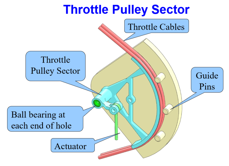
A favorite/terrifying bait was one from Don Day who was promoting a profile tolerance control for a bracket to follow the curve of a pulley to keep the cable in the groove. Anyone who has dealt with that problem knows that is a terrible idea and that it is misalignment between the pulley and the rest of the cable path that causes the cable to climb. If that's not dealt with it progresses to chew up the side of the pulley and wear out the cable. Once the escape is in progress that bracket will either wedge the cable, become just another sacrificial part for wear, or cause enough excess wear to part the cable.
Is this what you're talking about?
Pulley_sector_fdiuzi.png


John Acosta, GDTP Senior Level
 
3DDave,
I brought up FEA not as a distraction, but as a comparable case to give you a chance to either rationalize your position or understand why it's absurd. You failed at taking that opportunity. Instead, you mentioned that you "have seen case studies from FEA developers" (these were not comparing FEA Vs. no FEA so that's off-topic) and "worked with one engineer who was a developer for the P-element software", then you went into another off-topic distraction about P-elements vs. H-elements.

If all you care about is fast deliveries regardless of what you are being delivered, you are welcome to order parts from "quick-response manufacturing companies that can take in a model and return a part to the customer in less than a week, no GD&T at all". If you need quality and want to know what you are getting, order from competent suppliers that can make parts adhere to a proper controlling document.

When I changed badly done drawings of existing products, the one-off costs of readjustments paid off big time in the long run. A lot of unnecessarily tight +/- tolerances were eliminated. Less scrap, more reliable and less time-consuming inspection method. More rigorous control of functionally critical features. The non-critical features are controlled within looser tolerances, yet within robust tolerance zones. The manufacturing process didn't require considerable changes. The revisions applied only to new batches. The demand for these parts either remained stable or increased since.

"The point is that controls aren't useful on bad ideas and using controls doesn't make the application less bad."

This was not your initial complaint. You clearly said that the bad idea was the profile control, not the application:

"Don Day who was promoting a profile tolerance control for a bracket to follow the curve of a pulley to keep the cable in the groove. Anyone who has dealt with that problem knows that is a terrible idea"

Now you attempt to escape from it by criticizing the application. He didn't invent the application. He was suggesting a way to apply controls that actually do consider the assembly - by at least using datum features.
 
John,

Yes. If those pins ever guide the cables it's going to cause trouble. If only one cable pops from the groove it has a great chance to bind in between the pin and the pulley, locking the throttle in place. If the cable is repeatedly guided back into position, it will grind against the pin and the pulley, in a race between the failure of one cable or again popping out and binding, eliminating the apparent redundancy, making a partial problem into a total failure.

It also looks to be modeled incorrectly as motion in either direction will pull the opposite side cable over the sharp end of the pulley slot. All the "GD&T" expertise in the world doesn't help if the result is junk. It shows a lack of understanding of the requirement which should preclude suggesting any solution. Just doing a conversion is easy. Addressing the need takes work.

I am reminded of the very real failure on Alaska Air where the pitch trim jackscrew used "redundant" nuts, not noticing that as the primary nut wore out the load and wear was transferred silently to the backup. Because of the backup nut the failing threads in the primary were disguised until it killed a lot of people.

 
I recently saw some drawings here at work. I can't show them due to ITAR.
Major aerospace program.
One dwg has a lot of holes in it. The holes are dimensioned using ordinate dims coming from one corner,
The mating part with mostly the same holes that align to each other, it also uses mostly ordinate dims, but from a different corner.
Both dwgs use a little GD&T, but with datums from different places.
I have argued here that they should both be dim from same corner and using same datum.
I'm told "It doesn't make any difference" by Sr Engineers that told me they are very well versed in GD&T.
They are beyond retirement age, and should retire. ugh

Chris, CSWP
SolidWorks '20
ctophers home
SolidWorks Legion
 
Perhaps it makes no difference; it seems like a choice based on a very common goal which is to make production happy.

Almost always the correct answer is to use the face as a datum feature and create FCFs for the position tolerance on the holes with the implied simultaneous requirement to FCFs controlling the part profile with only the one datum feature reference. By using edges as datum features the edges typically end up with tighter controls than required. They have tight perpendicularity and flatness tolerances to make them suitable references, but if they don't tightly abut surfaces on other parts it's a waste of effort to do so.

Whatever passes through the holes is usually the common feature that indexes the parts and the part border is some configuration for convenience, not a functional interface.

It certainly is convenient to review the drawings if the offsets are identical to compare the two, but inspection and manufacturing should not be affected by that. What of the case of a cover on a large box? They share no corner in common. The ordinate dimension values cannot be identical if starting from edges, so it's just weird, not unworkable.
 
3DDave, you are talking around the issue again.
cthoper clearly stated that the holes on the two mating parts reference datum features from different corners, i.e. from non-mating edge surfaces.
So this is not a case of a simultaneous requirement to the face.
It is a case about people not knowing what they are doing.
This is what happens when the management thinks it's smart and cost-effective not to do anything to get designers to learn how to apply GD&T.
They are going to apply it anyway, doing it badly.
 
It's clear you don't read for information but looking for alternate facts.

But you must have a paragraph in Y14.5 that clearly says this is illegal. Otherwise, like you, it's only an annoyance.
 
Obviously you don't write in this thread to provide information but only trying to outsmart everyone.
Otherwise you would be paying attention to what cthoper told about how the datum features were selected, simply a bad practice.
After all your talk about looking at the requirements, do you need to be reminded that legality is not everything?
When your only consideration is legality per the standard, you are bound to end up with failures. In the case cthoper brought up, poor control of alignment between the holes that costs the same as an adequate one could. But now you have no problem with sloppy and ineffective work because it's legal.

If you need the standard to tell what common sense should have:

" 7.8 DATUM FEATURES
A datum feature is selected on the basis of its functional relationship to the toleranced feature and the requirements of the design. See Figures 7-4, 7-5, and 7-43 through 7-45. To ensure proper assembly, corresponding interfacing features of mating parts should be selected as
datum features. "

If you "read for information" you may find the above useful.
BTW, too bad you find this an "annoyance" but when you act smarty-pants someone is going to point out where you are wrong.
 
Since you are now so smart, what did I mean when I said that the edges should not be used as datum features because they were not functional? That in most cases like this the edges aren't functional and should not be used?

They are typically chosen for manufacturing comfort rather than product performance.

Still awaiting proof of being wrong.
 
Whatever happened to the "manufacturing comfort" of not having any datum features and geometric tolerances at all?
Wasn't it part of the approach you were promoting, to adjust a drawing to suppliers who "don't want to use it"?
Now they need holes positioned to non-functional datum features to manufacture the parts?

A bad practice is not needed for "manufacturing comfort".

Have you ever worked on a mill or watched how a machinist does it?
As long as the basic dimensions from the edges to the holes are on the print, you get all the "manufacturing comfort" you may need.
There is no need or reason to always fixture to datum features notated on the drawing.
The drawing could utilize the approach of a simultaneous requirement on the holes + edges, or if preferable the holes could be used as datum features referenced at MMC to control the edges. This will be considered later at inspection.
This is especially true if the location of the holes relative to the edges is not critical or tightly controlled.
Go and ask a machinist to show you that.
 
B, you still don't learn to read. "Manufacturing comfort" is not preferable, just frequently used.

That is separate from whether it was possible to influence cost. Put a piece of sheet metal into a Trumpf and I don't care what you put on the drawing the Trumpf is going to reliably produce the part. If the buyer knows that level of reliability is sufficient then additional requirements don't make the parts cheaper.

"The drawing could utilize the approach of a simultaneous requirement on the holes + edges"

I wrote that first. Again. But I specified the primary datum feature.

"Almost always the correct answer is to use the face as a datum feature and create FCFs for the position tolerance on the holes with the implied simultaneous requirement to FCFs controlling the part profile with only the one datum feature reference."

 
Status
Not open for further replies.

Part and Inventory Search

Sponsor