This is explained in my
complete pipe stress training course
Course agenda
download
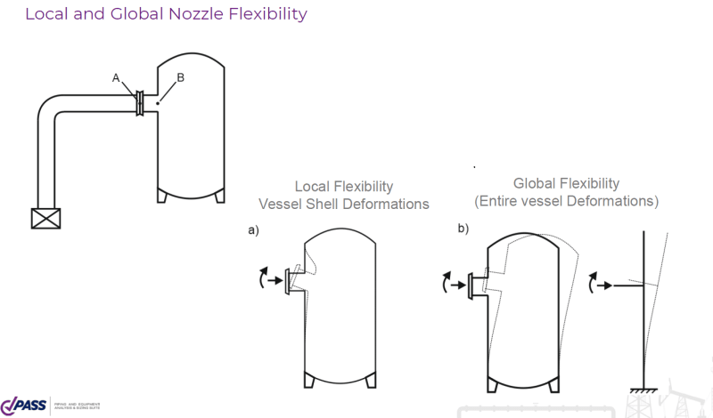
Short description. Nozzle can be modeled:
[ul]
[li]as an anchor, without flexibility[/li]
[li]as flexible restraint, with local nozzle to shell connection flexibiity[/li]
[li]as flexible restraint, with local and global vessel flexibiity[/li]
[/ul]
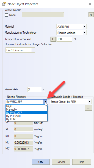
The flexibility of the nozzle to shell connection can be calculated using WRC 297 or BS PD 5500 or using finite element analysis (FEA) automatically
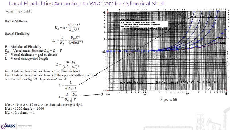
WRC 297 method has a lot of restrictions. Only radial nozzles, d/D<0.5, d/T>5, etc.
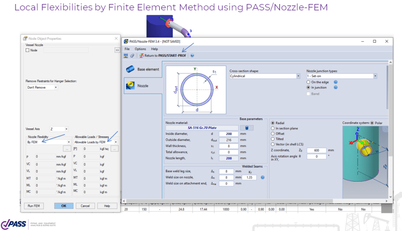
Finite element method has no restrictions and can be performed automatically.
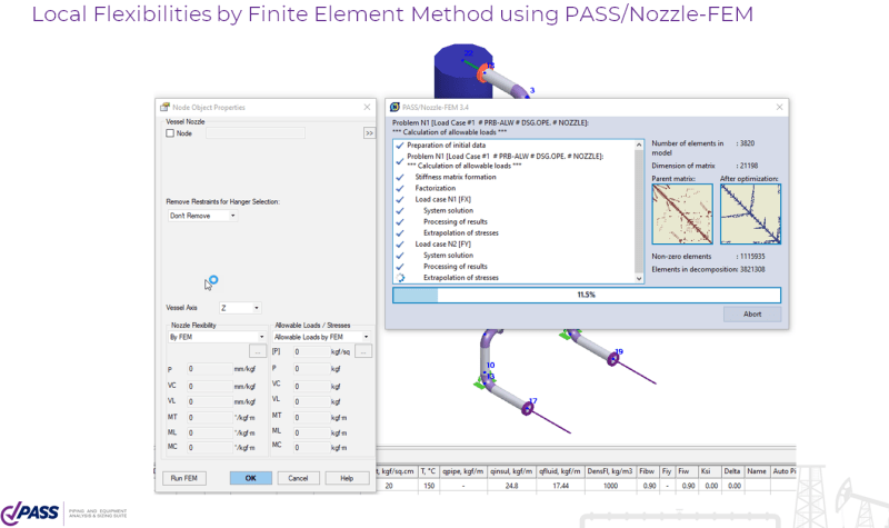
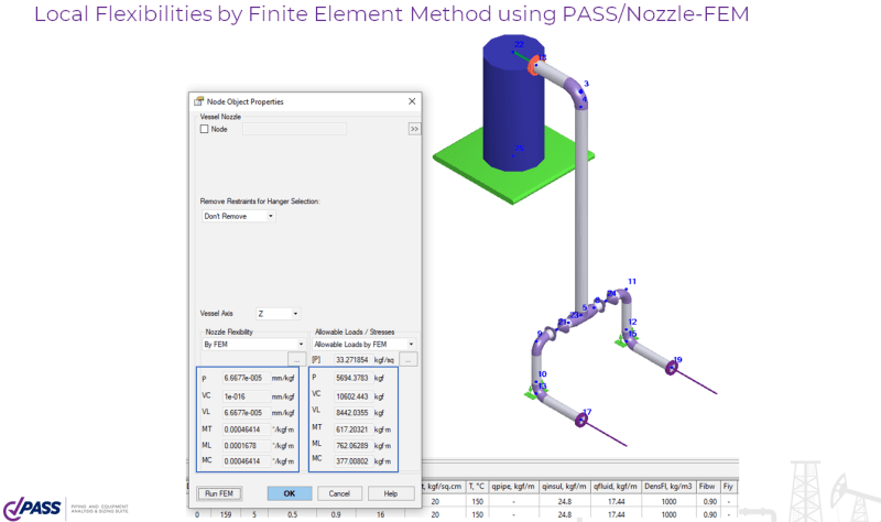
Need to select flexibilities FEM. Speciy the vessel and nozzle properties
Run FEM analysis
And receive the flexibiities (and also allowable loads or stresses in the nozzle after piping system analysis)
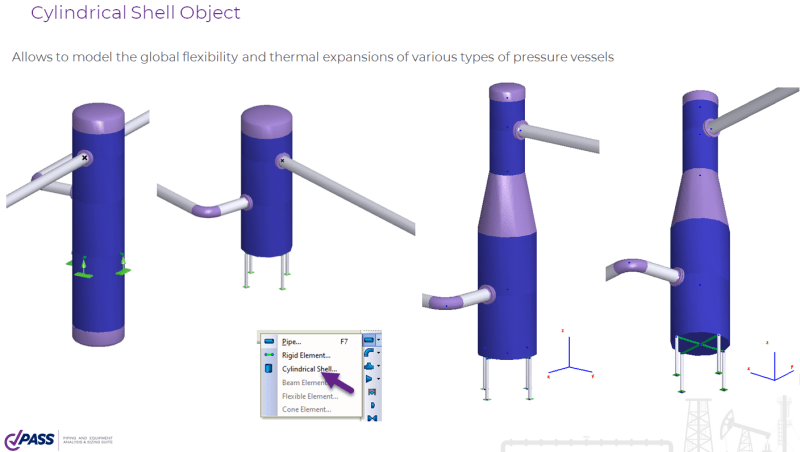
To model the global flexibility of the vessel you can use the cylindrical shell elements:
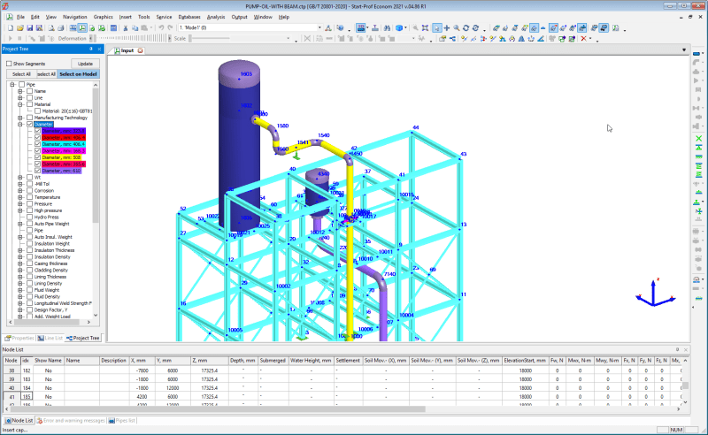
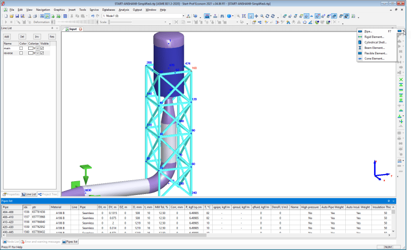
Sometimes legs of the vessel may be much more flexible than the vessel itself and nozzle to shell junction. And sometimes the steel structures can be more flexible than the vessel and nozzle. In this case need to make something like this:
or like this:
Hope it will be useful
I'm the PASS/START-PROF Pipe Stress Analysis Software Developer