Eng-Tips is the largest engineering community on the Internet

Intelligent Work Forums for Engineering Professionals

Nozzle loads reacted through heat exchanger girth flange 3

Status
Not open for further replies.

men8th

Nuclear
Jul 1, 2016
19
0
0
GB
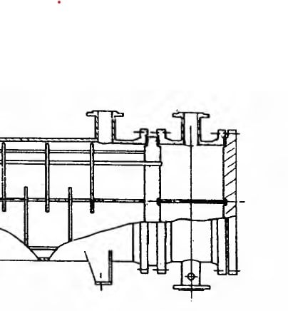
We are in the process of designing a large heat exchanger. It has two fixed tubesheets, for example TEMA type AEL. The tubesheets are "loose" and sandwiched between girth flanges on the shell and channel, similar to the image below.
Screenshot_2023-07-05_204643_inmzgl.jpg

The nozzle loads on the channel are considerable and the nozzles are oblique (hillside). When the nozzle loads are resolved around the centroid of the girth flange bolt group there is a moment which will attempt to rotate the channel about its axis.

As things stand, there is nothing to react the moment which is rotating the channel apart from the friction in the joint between the channel, tubesheet and shell. If the friction fails, the studbolts which attach the channel to the shell across the girth flange will be put in shear by the moment which is spinning the channel about its axis. Having fasteners in shear is not good design, and we do not want to be reliant on friction.

Has anyone come across this problem before, and are there any good design details which could be suggested. Obviously it would be possible to key or pin the girth flanges and tubesheets. I do not anticipate that the channel will ever be removed once the unit is in service. (Cover will be removed to inspect tube-side from time to time.)

Things we cannot do:
[ul]
[li]Weld the tubesheets to the channel or shell (materials problems)[/li]
[li]Change from two fixed tubesheets (client stipulation)[/li]
[li]Reduce the nozzle loads (constrained by other pipe layout issues)[/li]
[/ul]

Looking forward to a flood of good ideas!
 
Replies continue below

Recommended for you

men8th, consideration of the effect of nozzle loads on components other than the shell to which the nozzle is attached is very rare in my experience. Nevertheless, if you believe it must be considered, then it must be.

If you are only concerned with a moment about the channel axis, and do not wish to consider friction in the bolted joint then it seems some form of keying is your only option. Perhaps a full diameter tubesheet or perhaps lugs attached to the girth flange and tubesheet OD could be useful.

But: Are there bending moments applied to the bolted joint that are of a magnitude that cannot be ignored? Keying may not address such.

Off topic, but I would be very reluctant to employ a gasketed joint on the shell side. If the shell-tubesheet gaskets were to leak it seems there is just about nothing you could do about it. Do you have experience with such a construction?

Perhaps your metallurgies can be made compatible by cladding the tubesheet?

Regards,

Mike


The problem with sloppy work is that the supply FAR EXCEEDS the demand
 
I don't understand why a TEMA AEL exchanger would have a shell-to-tubesheet flange like shown in your sketch. This would create a gasketed joint between the tubesheet and the shell flange that you wouldn't have access to in case the gasket ever needed to be changed out.

Normally on an AEL fixed-tubesheet design the tubesheets are both welded directly to the shell on as shown in the photos below:


The normal practice for heat exchangers is to just assume that the piping loads do not transmit to the girth flanges or to the saddle supports. Not exactly logical but it certainly makes things convenient.


-Christine
 
I'd add that most of the time the reason fixed tubesheet exchangers are specified is to eliminate gasketed joints on the shellside.

As to never dropping the channels, I'd sure hope not. That would almost certainly start the shell gaskets leaking...

The problem with sloppy work is that the supply FAR EXCEEDS the demand
 
If the OP expects that channels will never be removed then an alternative might be to use an NEN fixed-tubesheet design which eliminates gasketed joints on both sides of each tubesheet. If dissimilar welds are a concern you can apply cladding/weld overlay to either side of each tubesheet.


-Christine
 
Thanks for your suggestions all. In case it helps, to clarify:
[ul]
[li]There is metal-to-metal contact between the tubesheet, channel and shell. The seal is not a gasket in the traditional sense.[/li]
[li]We have experience with a similar design which has been in-service for a long time so at least there is some confidence this thing will work when built![/li]
[li]SnTMan, we agree that the other bending moments about the bolted joint could be a problem - we are considering them in the design. It's because we started doing this more detailed analysis that we determined that there was no load path (other than friction) for the rotation and started questioning whether there should be[/li]
[/ul]
Interesting to hear that nozzle loads are seldom analysed beyond the shell attachment, although it confirms my own experience. Scanning through the literature, the only other place nozzle loads seem to get routinely considered are in the design of the saddles.
 
If you are otherwise confident of your design, perhaps your way forward is to key for the tangent moment and just provide more bolting than required for pressure loads to address the bending.

Nozzle loads are generally small compared to pressure loads and so are usually neglected as to other components.

The problem with sloppy work is that the supply FAR EXCEEDS the demand
 
I would try to reduce the piping loads if they are excessive as mentioned above. I would not think they would be excessive as long as they do not overstress the shell of the channel at the connection point due to local loads determined by a FEA or WRC 107/297 methods of analysis.

Usually in piping systems girth flange loading is analyzed per ASME methods in stress analysis programs such as Caesar II. However I don't recall the circumferential torsional moment input into the equation - but only the longitudinal bending being the main factor. I believe this is because the bolt will take up the shear with no problem. There are many flange bolts with alot of area to take shear loading at a large centroidal distance so the shear stress will be very small even with high torsonional loading of the girth flange. In fact structural bolts are designed in most cases to be totally shear connections and there is an allowable for bolts in tension and shear simultaneously.

Furthermore I would not check for loading beyond the connection of the piping to the channel. If you are concerned with the loading on the exchanger other than that you should just make a table in your specifications to the heat exchanger supplier of your calculated piping loads (Fxyz and Mxyz) and let them make sure the loads are designed for.
 
Status
Not open for further replies.
Back
Top