Hello everyone,
I have been trying to model in ABAQUS (I am new to the software) a simple supported reinforced concrete beam. I have used solid elements for the concrete beam and wire elements for longitudinal rebars and stirrups.
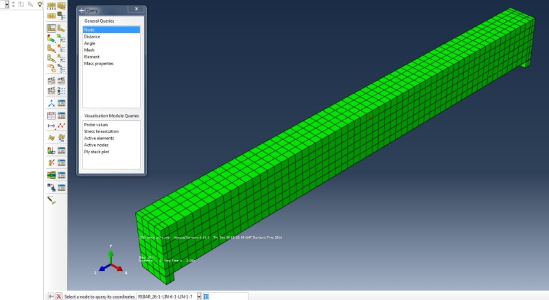
The simulation keeps failing for 'numerical singularity' issues. I have checked my boundary conditions and constraints and everything looks fine. Both supports have U1=U2=U3=0 and all the reinforcement is constraint to the beam with an 'Embedded region' type constraint. The problem appears to occur on the node located on every longitudinal rebar (24 rebars along the perimeter of the section) at midspan. The red dot in the picture below shows the node where the singularity occurs, i.e. on the rebar at midspan. There are other 23 failures occuring at midspan and corresponding to the remaining rebars.

Do you have any suggestion on what the issue might be?
I appreciate your help.
Thank you very much.
Regards,
Martino
I have been trying to model in ABAQUS (I am new to the software) a simple supported reinforced concrete beam. I have used solid elements for the concrete beam and wire elements for longitudinal rebars and stirrups.
The simulation keeps failing for 'numerical singularity' issues. I have checked my boundary conditions and constraints and everything looks fine. Both supports have U1=U2=U3=0 and all the reinforcement is constraint to the beam with an 'Embedded region' type constraint. The problem appears to occur on the node located on every longitudinal rebar (24 rebars along the perimeter of the section) at midspan. The red dot in the picture below shows the node where the singularity occurs, i.e. on the rebar at midspan. There are other 23 failures occuring at midspan and corresponding to the remaining rebars.

Do you have any suggestion on what the issue might be?
I appreciate your help.
Thank you very much.
Regards,
Martino
