Continue to Site

Eng-Tips is the largest engineering community on the Internet

Intelligent Work Forums for Engineering Professionals

  • Congratulations IDS on being selected by the Eng-Tips community for having the most helpful posts in the forums last week. Way to Go!

Numerical solution of simple model doesn't match the analytical solution 2

Status
Not open for further replies.

FerriteAlpha

Civil/Environmental
May 4, 2019
6
Hello everyone,

Yesterday I experimented a little bit with abaqus in order to understand different constraints. I noticed, that the numerical solutions for a simple model are very different to the results that I expected.
I created a VERY short column with an I-Shape cross-section. Now, since the column is so short that buckling doesn't occur, I expect the axial resistance to be N=A*fy, where A is the area of the cross-section and fy is the strength of the material. In this case I used a simple ideally plastic behaviour of a S235 steel (fy=23.5kN/cm²).

The cross-sectional area of my attached model (if the area is duplicated, since only one half is modelled) is around A=744mm²=7.44cm². Therefore the analytical plastic axial force is N=7.44*23.5kN/cm²=175kN. Creating the model with S4 elements leads to the right solution. With the model in the attached input-file I get around 120kN (duplicated Reaction force). So it is far too low. On the other hand I created the whole cross-section with C3D8R elements without using the symmetry plane. Then the axial force was around 200kN. So it was too high. I am honestly very confused. I'm not sure if its because of the boundary conditions or constraints or something else... I just can't figure it out...

It would be great if someone could help me out with this one.
 
 https://files.engineering.com/getfile.aspx?folder=7962c15f-1b54-4e8d-a567-1daadea1b84e&file=Test.inp
Replies continue below

Recommended for you

So basically shell elements (S4) give you correct results and solid elements (C3D8R) provide wrong solution, right ? This may be caused by low quality of 3D mesh. Try using full integration elements, refine the mesh (I can't see your model now but if you don't have at least 3 or 4 elements per thickness, you should change it), make it as regular as possible (structured meshing algorithm) and maybe use second order elements. Make sure that there are no distorted elements.
 
Thank you FEA way. I'm going to try all of that out!
 
I tried everything. The mesh in the first .inp I posted is already pretty fine and structured. So this shouldn't be the problem. Also, since the "column" is only 10cm long, there shouldn't be any bending involved, so locking should not be a problem as well. However, I tried it with full integration, with quadratic functions and quadratic full integration. The result doesn't change which leads to the conclusion, that the mistake has to be in the boundary conditions or constraints. Although they are the same in both models. :-(
 
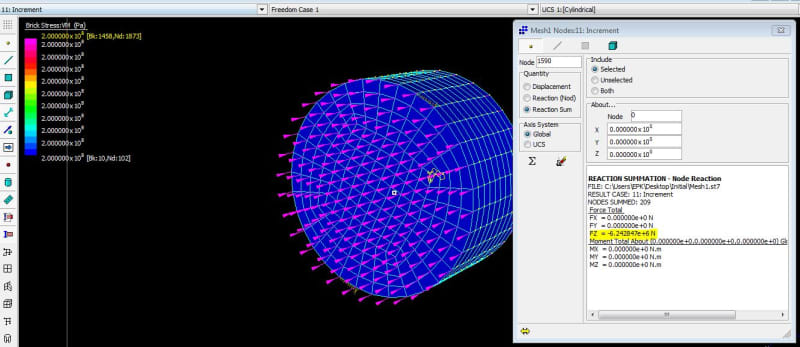
This is very straightforward - as you can see below in Strand7 (software I work for and develop together with our team in AUS), an example of a CSS with a radius of 0.1 m, length of 0.1 m, and with steel say yielding at 200 MPa, gives a yielding force (axial) of 6.28319E+06 N.

As seen below the total axial reaction (using displacement control, thus enforced displacements on one face, pink arrows in the image), is exactly that and the whole section has yielded at this load with 200 MPa all over the section at yield. Now all general purpose NL FEA packages can predict this using HEX8 or HEX20 elements (no need for reduced integration) in pure axial loading so very easy.

Capture_qwaja1.jpg
 
I know that this is the solution that should come out of the simulation. But it doesn't, which is exactly the point. Only the shell model gives me the right solution. Not the one with hex elements, where I'm way above or below the expected solution, depending on if I use symmetry-BCs or not. Maybe I can figure it out tomorrow.
 
Try modeling this as a single part instead of two separate instances comnected with tie constraint. Also be careful with that coupling connector. It seems that some nodes (the ones that belong to the symmetry BC region) may be overconstrained. Try distributing coupling instead of kinematic as it’s too stiff.
 
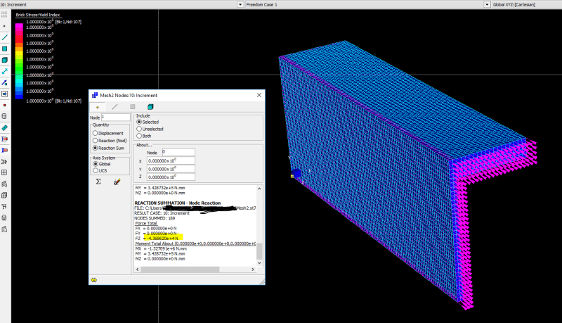
Here are the results for the not common cross section you have (correct as it should be and equal to as shown below see total reaction of 44000*4 N (1/4 sym. so times 4).

So the boundary condition to use (skip and RBE2 or RBE3 constraints) are (1/4 symmetry): bottom face at mid web height in the image use Y displ. = 0, for the large face at the symmetry of the web fix X=0, and finally the two ends (z= 0 and 100 mm) use on one enforced displacement of Z=-0.15 mm, and Z=0 mm on the other. At the common edges for these faces it is important that the BC are added (not sure exactly what abaqus does), I enforce this since I am applying BC straight on the mesh nodes in Strand7 so I know what the solver sees, and so I know what I am doing exactly. So just follow these steps and it should be fine (mesh is all conencted so not using any tie-like constraints, evenhough that should not cause any problems, and not using RBE2 and RBE3 constraints, just simple/standard BC as explained above).

Capture_ycrccz.png
 
Hi everyone,
please excuse the late reply. Thank you for your input.

It seems, that the overconstrained nodes were the problem in this case. I didn't expect them to have such a huge impact on the results.

Thanks again! :)

 
Status
Not open for further replies.

Part and Inventory Search

Sponsor