Continue to Site

Eng-Tips is the largest engineering community on the Internet

Intelligent Work Forums for Engineering Professionals

  • Congratulations KootK on being selected by the Eng-Tips community for having the most helpful posts in the forums last week. Way to Go!

Nut plate Counterbores

Status
Not open for further replies.

SBlackBeard

Aerospace
Apr 21, 2022
12
Why are nut plate counterbores they depth they are? Or if OEMs find them acceptable, how do they balance nut interference and threads in bearing?

It seems obvious that nut plate counterbores are .0625 because that matches a bolt grip, but it seems like looking at the specs, it is too short because of partial threads on the bolt.

Every fastener spec has a “partial threads” region outside the bolt grip before the threads are full depth. You obviously don’t want to have the fastener partial threads interfere with the threads on the nut, which would mean you would achieve torque before developing preload. Those partial threads are typically 2p. Adding to this, you can only increment a fastener by grips aka divisions of .0625. It seems like the counterbore should allow for both partial threads and the full range of a grip. Otherwise, you end with something like the following example: .150” material stack - round down to .125 grip and have threads in bearing or round up to .1875 grip and possibly have interference with the nut and no preload. The result in either case is not ideal, I’d prefer to have my two sheets to be fully engaged with the shank of the fastener and develop full preload.

As an interesting note, Hi-lok collars have nearly double the counterbore and it scales with fastener thread pitch.
 
Replies continue below

Recommended for you

I have difficulty understanding "nut plate counterbore" ? I know what an anchor nut is, and what a counterbore is, but not together ...

"Hoffen wir mal, dass alles gut geht !"
General Paulus, Nov 1942, outside Stalingrad after the launch of Operation Uranus.
 
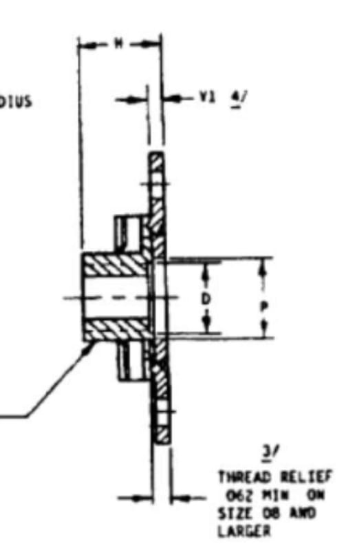
rb1957 - sometimes it is called thread relief, like on this old MS21076 nut plate spec:
68D94B63-4695-4661-A736-1E349CE0D6A3_xyjdqo.jpg
 
Ok, had never noticed this ! Had never looked inside an a/nut before ...

yes, thread relief (as per note 3) ... seems to have an "odd" relationship with V1 ?

"Hoffen wir mal, dass alles gut geht !"
General Paulus, Nov 1942, outside Stalingrad after the launch of Operation Uranus.
 
The relief in the nutplate threads is there to ensure the mating bolt... with shank... can penetrate thru the material stack-up with out bottoming the threads in the NP barrel... and to ensure that the shank [with thread runout] can fully protrude thru the stack-up [with slight stack-up tolerances considered] and should ensure that NO bolt-threads are in-bearing.

Nutplates with NO counterbore are relegated to small diameters and short stack-ups... for small bolts or full threaded screws.

NOTE. Some nutplates specs allow for multiple '-length' nut barrels with matching deeper counter bores for non-intuitive, but practical, reasons. SBB: WHY??? Think about it for awhile... everyone else... no hints.

Regards, Wil Taylor
o Trust - But Verify!
o For those who believe, no proof is required; for those who cannot believe, no proof is possible. [variation, Stuart Chase]
o Unfortunately, in science what You 'believe' is irrelevant. ["Orion", HBA forum]
o Only fools and charlatans know everything and understand everything." -Anton Chekhov
 
WKTaylor - agree, intent is to avoid threads in bearing and bottoming the threads in the nut plate barrel. However, consider the following example - it just doesn’t seem like the standard nut plate has sufficient thread relief.

Suppose you have a 1/4-28 bolt with max two incomplete threads called out on the threaded portion of the bolt. On a 28 TPI bolt, that length is .071. In addition you will most likely have a material stack that does not exactly match a grip length. Let’s say you have a material stack that is halfway between grips - let’s say .281, so halfway between .250 and .3125. In this case if you pick a .3125 grip you would need to have thread relief for .071 + .031 = .102, which nut plates do not have, so you’d have bad preload/bottom out the threads on the NP barrel. Or grip down to a .250 and have .031 of (partial) threads in bearing.

As an interesting comparison, hi-loks of the same size have .122 of thread relief, so they would appear to dodge this problem.
 
Well, hmmm, these nutplates have been used for many decades, presumably without things coming apart, so why is it a problem now?
 
SWComposites - good question, but I don’t really know all the circumstances under which those worked before. Maybe most of those nut plates that posed no problem were installed to a non-load bearing carrier outside the loaded panels, or maybe the analyst checked a reduced bearing area in accordance with the amount of threads in bearing. Or maybe they weren’t used in bearing critical joints. There are a lot of possibilities as to why it would not be a problem in existing designs but could be a problem in other areas. I think the point I’m making is: it seems negligent to assume no threads in bearing and good preload in a standard nut plate where that assumption does seem reasonable with a hi-lok. Maybe that’s overly conservative?
 
Are you concerned with flush head or protruding head fasteners going into nutplates? With protruding heads, one can just put a washer under the head if needed.
 
Good point - mostly flush head. Washer is a good solution if that wasn’t the case.

Still, it would be fantastic if most nutplates had more thread relief. It is very simple to consider hi-loks when, by design, they don’t bottom out and don’t have threads in bearing, where it appears nut plates need more nuanced consideration.
 
Nutplates are typically used when the joint must be removable, in which cases Hiloks wont work. Or they are used for blind installations when blind fasteners are not preferred.
 
Totally understood - my contrast with hi-loks is because they make design considerations simple and a higher capability joint. I need to use flush head, I need to use nut plates, so I’m left with possibly bad preload or threads in bearing. The lesser of the two evils is threads in bearing, but I’m all ears for other ways to get out of this OR rationale as to why that’s not the right way to look at it and a knockdown isn’t necessary.
 
Nutplates are typically and should only be used in less critical joints. So,
- you should not have MS=0 in bearing at ultimate,
- it should not be a fatigue critical joint,
- you might have a small bit of threads in bearing, but those threads are next to the nutplate, and not at the joint shear plane where the bearing stress concentrates (no, bearing stress is not uniform thru the thickness in a single shear joint), so its probably not an issue.
 
Also... SBB... ahhh the designer's dilemma.

You/we've danced around this... WHAT [NAS, MS, AS, etc] Part Number nutplate are you visualizing for this question. You are aware there are many configurations of NPs available, correct...?

IF precision grip VS NP counterbore cannot be attained... and the bolt has to be fully protruding thru the stack-up... and still prevent 'thread-bottoming'... there are [2] primary solutions... other-than washers under a protruding bolt head... thus...

(a) Install/use a Nutplate with an extra-long thread barrel and extra deep counterbore... and a bolt with 'long-threads'.
(b) Install a shim under the base of the nutplate... co-drilled/riveted with the nutplate, thus...
Hand-made sheet metal shim
NAS463 NUT SPACER, PLATE, PLAIN
NAS500 SPACER, NUT, PLATE, COUNTERSUNK
NAS1195 SHIM, MINIATURE ANCHOR NUT

PS1. A secret handshake You might not be aware of...

Say that You are assembling a stack-up of [4] 0.063** thick sheets of aluminum. Sooooooo, the combined thickness of the stack-up is [0.063] X [4] = 0.252, correct...???? Beeeeep... wrong answer...

The actual stack-up... assuming adequate corrosion protection [primer-film both sides of each sheet, minimum]... will be roughly [0.063 + 0.001 + 0.001] X [4] = 0.260... correct!

Add in a thickness allowance for slight thickness of sealant between layers [0.001 X3]... and the stack-up for all practical purposed could amount to +0.263-ish, minimum. This is why You always have to ensure bolt-shank protrudes thru the sheet metal stack-up... and never forget that micro-SETTLING may occur after assembly, resulting in a microscopic stack-looseness. Daaaannng.

**NOTES1.
[A] Also sheet metal, made-to 'normal' +/- tolerances are surprisingly variable... and the standard tolerance sheet metal can be surprisingly bowed and wavy and have variable thickness, over wide areas... Oooohhhhhh...unless premium sheet metal is procured at significant cost.
And clad [~0.0015 thick, each-side] sheet aluminum is actually over-all 'weaker' than bare sheet aluminum, same alloy/temper/thickness.

My head hurts.

Regards, Wil Taylor
o Trust - But Verify!
o For those who believe, no proof is required; for those who cannot believe, no proof is possible. [variation, Stuart Chase]
o Unfortunately, in science what You 'believe' is irrelevant. ["Orion", HBA forum]
o Only fools and charlatans know everything and understand everything." -Anton Chekhov
 
thanks Wil - I didn't want to go down the deep dark wormhole of sheet tolerances, countersink depth tolerances, sealant and primer thicknesses, etc.
 
SBB... I've had many discussions like this in past years...

Another secret handshake...

Hi-Lok Pins and collars [threaded install] were developed with post production in-mind. HLs were intended to replace the standard hand-installed swaged-collar lock-bolts... and larger conventional bolts/washers/nuts used in permanent structural applications... which meant that the early use for HLs would be primarily mods and repairs and 'special assemblies'... hence the range of sizes/oversizes and collars... and uniquely/sneakily... these collars and pins were designed with high variability in mind, IE: Pins with long-threads and collars with deep thread counterbore recesses; and collars high 'break-off torques' [which presume that the slightly 'loose parts stack-ups' would be very tight prior to parts 'settling slightly over time'.

Fast forward to automated assembly... suddenly Hi-Lok pins/collars became the standard 'lock-bolt'... since their assembly sequence was a lot more automation-friendly than swaged-collar lock-bolts [plus a whole-lot more sizes and features]. For many reasons over-the-years, these automated production parts adopted generational improvements... 'feature-functions' friendlier for production automation... and allowing tighter fits for fatigue durability, etc... and have become distinctly different from their early [grandpas'] post-production-era parts [which are still very useful].

In conclusion... there are actually [2] distinct families of Hi-Loks: (a) 1st generation 'conventional' for post production and general hand Assy; and (b) newer multi-generational versions suitable only for automated assembly for new production parts.

OK, OK, OK... Hi-Loks are now a 'generic term' most often used to describe a mind-blowing array of evolved pins and collars of similar function... and some designed/made by companies other than licensee's of the Hi-Shear product lines.
Hi-Loks
Hi-Tigue
Hi-Lite
and-so-on... to name a few


Regards, Wil Taylor
o Trust - But Verify!
o For those who believe, no proof is required; for those who cannot believe, no proof is possible. [variation, Stuart Chase]
o Unfortunately, in science what You 'believe' is irrelevant. ["Orion", HBA forum]
o Only fools and charlatans know everything and understand everything." -Anton Chekhov
 
Also, don't forget that the Nutplate is installed on a sheet of some thickness, so I think you could also include the sheet that it is attached to in your "counterbore" depth stack-up.
 
Status
Not open for further replies.

Part and Inventory Search

Sponsor