Continue to Site

Eng-Tips is the largest engineering community on the Internet

Intelligent Work Forums for Engineering Professionals

  • Congratulations KootK on being selected by the Eng-Tips community for having the most helpful posts in the forums last week. Way to Go!

NX 11.0: Wrong beam deflection results

Status
Not open for further replies.

thakurai

Mechanical
Oct 11, 2017
14
Hi,
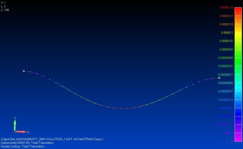
I am doing a simple problem of a beam fixed at both ends and carrying a uniform distribiuted load, material is steel. The results given by NX are different from the results I get using beam deflection formulas (Theoretical).
In attachments I have attached the beam problem, Beam theory formulas used to calculate deflection and results given by NX.
Since the Moment of Inertia, Modulus of Elasticity values are taken as given by NX itself, and also values of load and beam dimensions are displayed by NX itself , it does not make much sense why both the results are different.
Deflection (Y) given by beam theory is : 1.350E-5 mm and by NX is 2.286E-5 mm which is an error of 69 %.
Whereas the results for Bending stress is coming exactly same from both theory formulas and NX. Can anybody explain why am I getting theses kind of results.
Thanks,
Ashwani Thakur.
 
 http://files.engineering.com/getfile.aspx?folder=dd8c94e9-ed9d-459c-955f-d43af4f04332&file=NX11.0_Beam_deflection.PNG
Replies continue below

Recommended for you

This does not appear to be a FEMAP issue. Perhaps you should post this in the 'Siemens: UG/NX' forum.

John R. Baker, P.E. (ret)
EX-Product 'Evangelist'
Irvine, CA
Siemens PLM:
UG/NX Museum:

The secret of life is not finding someone to live with
It's finding someone you can't live without
 
i'm surprised your deflected shape doesn't show reflex (where the moment is zero).

another day in paradise, or is paradise one day closer ?
 
Posting the .dat file would make it possible to understand the difference.

Regards,

Joe
 
forget my post ... looking closer I can see zero slope at the supports (proper for fixed supports).

I think the problem is shear deflections ... your web is quite large (3m long, 1/3rd m high) ... shear deflections need to be added to the flexural deflections you're using)

another day in paradise, or is paradise one day closer ?
 
how did you model this ... 1D beam element ? plates ? 3D solids ??

I'd've thought that the 1D beam element should match the beam theory.

another day in paradise, or is paradise one day closer ?
 
@ rb1957 Yes I have modeled it using beam elements only. That's why I got confused that why the results are not matching the beam theory results.

Thanks.
 
maybe the beam element formulation includes shear deflections ? try with zero shear area.

else calc the deflection due to shear

another day in paradise, or is paradise one day closer ?
 
The difference is beam theory assumption. The hand equation that you show is for the bending deflection only, that assume there is no shear deflection in the beam. The Nastran default when a PBEAML is used, is to include shear flexibility. If you add shear flexibility term to your equation it will match. The other option is to set the shear flexibility in Nastran to zero and then the answer will match your current hand calculation.

NX has written the following PBEAML property:
$* Property: PBEAML1
$* Section: I(1)
PBEAML 1 3 MSCBML0 I +
+ 340.0000250.0000250.0000 20.0000 20.0000 20.0000 0.0000 YES+
+ 1.000000340.0000250.0000250.0000 20.0000 20.0000 20.0000 0.0000

If you use "echo=punch" then you will see Nastran converts that to the following PBEAM:

PBEAM * 1 3 1.60000000E+04 3.01333333E+08
* 5.22833333E+07 0.00000000E+00 2.18666667E+06 0.00000000E+00
* 1.70000000E+02 1.25000000E+02 -1.70000000E+02 1.25000000E+02
* -1.70000000E+02 -1.25000000E+02 1.70000000E+02 -1.25000000E+02
* 3.75000000E-01 5.20833333E-01 0.00000000E+00 0.00000000E+00
* 0.00000000E+00 0.00000000E+00 1.33333333E+12 1.33333333E+12
* 0.00000000E+00 0.00000000E+00 0.00000000E+00 0.00000000E+00


If you set the shear factors(* 3.75000000E-01 5.20833333E-01) to zero and use that property entry, which will look like this:
PBEAM * 2 3 1.60000000E+04 3.01333333E+08
* 5.22833333E+07 0.00000000E+00 2.18666667E+06 0.00000000E+00
* 1.70000000E+02 1.25000000E+02 -1.70000000E+02 1.25000000E+02
* -1.70000000E+02 -1.25000000E+02 1.70000000E+02 -1.25000000E+02
* 0.00000000E+00 0.00000000E+00 0.00000000E+00 0.00000000E+00
* 0.00000000E+00 0.00000000E+00 1.33333333E+12 1.33333333E+12
* 0.00000000E+00 0.00000000E+00 0.00000000E+00 0.00000000E+00

noshear_results_neqkec.jpg


I have attached the modified dat file for you to try. Also the note below is from the PBEAM documentation in the QRG, note 13:
13. The shear stiffness factors K1 andK2 adjust the effective transverse shear
cross-section area according to the Timoshenko beam theory. Their default
values of 1.0 approximate the effects of shear deformation. To neglect shear
deformation (i.e., to obtain the Bernoulli-Euler beam theory), the values of K1
and K2 should be set to 0.0.

Regards,

Joe

 
1) are those factors fixed or dependent on geometry ?

2) can you see them if using NX thru FeMap ? (maybe we've found a FeMap angle ?)

3) If you zero the shear area (in the FeMap property input) does that zero these factors ?

another day in paradise, or is paradise one day closer ?
 
Hi can can someone share a reference about how to calculate the shear deflections in case of an I beam fixed at both ends. I googled and couldn't find a reliable formula or equation to find it using Timoshenko beam theory.

Thanks,

Ashwani Thakur.
 
Status
Not open for further replies.

Part and Inventory Search

Sponsor