Continue to Site

Eng-Tips is the largest engineering community on the Internet

Intelligent Work Forums for Engineering Professionals

  • Congratulations waross on being selected by the Eng-Tips community for having the most helpful posts in the forums last week. Way to Go!

NX 11 Pre/Post (Old AdvSim) 2D Mesh Refinement

Status
Not open for further replies.

vcolella

Mechanical
Jun 21, 2018
12
I'm having a hard time trying to refine 2d meshes in NX 11 Pre/Post (formerly known as Advanced Simulation). I'd like to know, what is the ideal workflow for this kind of meshes ?

Most of the times when I cannot get the mesh I want with typical FEM tools, I end up having to split the polygon bodies in the right way to manually mesh them. And even then, it's still a pain. "2D Mapped Mesh" rarely works, forcing me to apply a million mesh controls.

What am I missing ?
 
Replies continue below

Recommended for you

In case of complex geometry it's a standard procedure in all programs to divide models into simpler shapes (so called partitioning) and then mesh them using appropriate techniques. Fully automatic algorithms can only free mesh faces and if you want to have regular grid you must simplify the geometry. Mapped meshing is a special kind of structured meshing that can only be applied to very simple shapes bounded by 4 edges. So in order to use it in most cases you must utilize partitioning.
 
Well, I guess there's no running from it then. Thanks !
 
can you show us something of what your problem is ?

I'd've thought you can define regions on body/surface and define a mesh within those regions then when you mesh the surface/body you "should" get a consistent mesh ?

another day in paradise, or is paradise one day closer ?
 
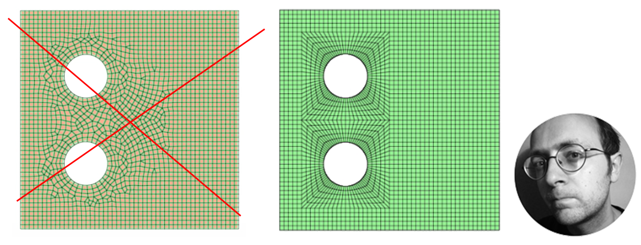
Imagine something like a plate with multiple holes in it. Looking at the image below, if I use the "Mapped Hole" mesh control, I get something like the mesh on the left. What I'm trying to get is the mesh on the right. :

thumbnail_map_mesh_plate_2_holes-e1478525882287.png

(source:
When you talk about defining a Region, do you mean it at the FEM file or CAD file ? In the FEM file, the best I could do was to create a Circular Imprint, but that didn't make that much of a difference in comparison to the "Mapped Hole" result.

Keep in mind that the holes are just an example of my problem, that is, not being able to divide my surfaces on the go in whatever way I want to manually refine my meshes.
 
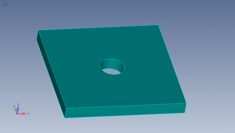
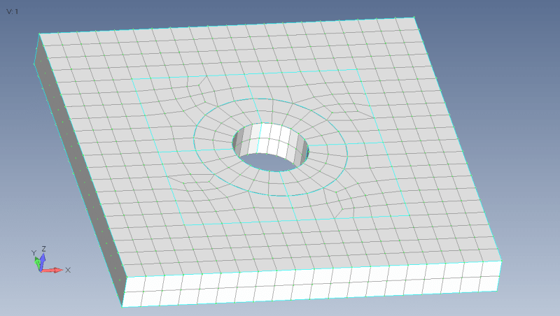
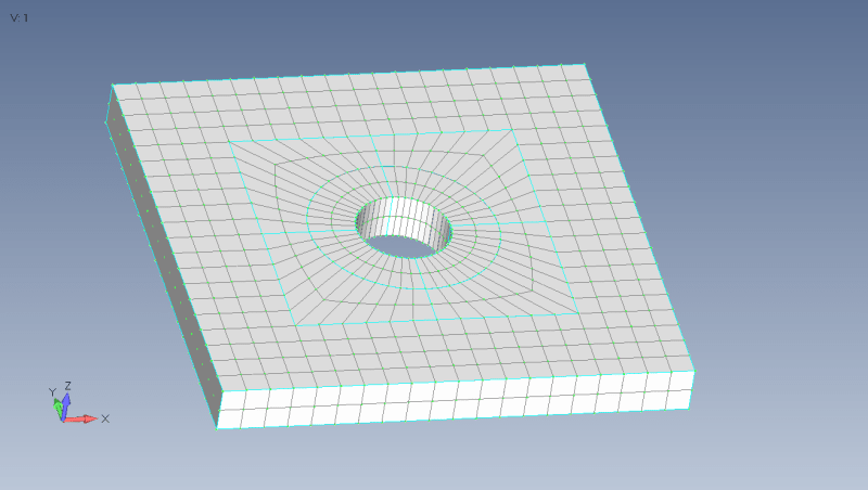
I`m not NX user but I think that you should chop geometry onto regular sweepable blocks to achieve neat regular mesh. Put mesh sizes on selected curves manually.
In addition check how distorted regular mesh at third picture. Regular mesh is not good in any cases, refinement only around holes, like at second picture, look like good choice.
1_zipj5f.png

2_blbcsd.png

3_iqhe2t.png
 
Thanks karachun, that's what I was trying to do. I guess the easiest path in NX 11 to chop the geometry would be to create sketches in the "Modeling" application and then apply "Divide face" with the sketch to obtain multiple faces. Then, and only then, you would have some kind of boundary in the geometry to achieve better manual refinement. I was looking for a quicker/shorter workflow, like in Femap, but I guess there isn't one.
 
I would actually not be surprised if the mesh to the left is better from a mathematical point if view. There are a few triangles with is bad but the quads are generally more quadratic then in the right mesh.
The right mesh may look better but I would not bet on it producing the most acurate solution.

Just a thought.

Thomas
 
Status
Not open for further replies.

Part and Inventory Search

Sponsor