Continue to Site

Eng-Tips is the largest engineering community on the Internet

Intelligent Work Forums for Engineering Professionals

  • Congratulations IDS on being selected by the Eng-Tips community for having the most helpful posts in the forums last week. Way to Go!

NX 12 Kayak Modeling

Status
Not open for further replies.

AnAngryScotsman

Aerospace
Oct 15, 2019
8
Hello,

This is my first post here so apologize for any mistakes.

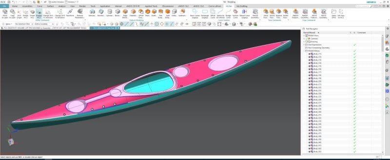
I am currently trying to recreate the model of a kayak (attached) as I am looking into journaling for customisation - therefore require a .part/similar rather than the .stp format I currently have it in.

However, I am struggling with how to go about modelling it - specifically the curved section on top.

Not sure how much detail I should include here, but any further information I am happy to provide.

Thanks!

 
Replies continue below

Recommended for you

What system did the STEP file come from? Seems like it imported as sheet bodies. Do you need to modify the geometry? Otherwise you could try and Sew it together and thicken.

Clipboard01_iibnme.jpg
 
Hello,

I see you have realized my exact problem! I have no access to the system the part came from, I believe it was made in another software package - however, the original designer is being very unhelpful.

Yes, my main goal is to edit the geometry to add a level of customization to the part - as if it was to be manufactured (in theory).

Even trying to work out the cross-sectional dimensions is proving to be difficult, just because of the way the model has been designed and the format I received it in
 
Why don't you use Synchronous Modeling?
I was able to make changes to the step model using that.

I would advise first, to use the external translators to convert it to a prt file. In there you can tell the translator to optimize and Sew the faces.
It will not work for all bodies but at least you will have a model with less separate bodies.

Ronald van den Broek
Senior Application Engineer
Winterthur Gas & Diesel Ltd
NX9 / TC10.1.2

Building new PLM environment from Scratch using NX12 / TC11
 
Step files are plain text. Most often (?) the exporting system will be printed in the header. In this case it's Autodesk Alias.
Alias is a dedicated and very capable Surface modeler , primarily used for Industrial Design.
Alias can create very-very good surfaces, surfaces that can be used straight away.
But, Alias also lets the user create completely un-usable surfaces. Surfaces that no CAD system can handle straight away.
In this case i would say that this is good quality. Most surfaces are single patch which often tells that the designer knows what he is doing.
All surfaces i looked at are true four sided , none have "squished" pole structures. Tiny surfaces missing in the bow/ stern but which can be added in NX without changing the design.
-surfaces without "squished pole structures" can be thickened.

But, the result will still be imported data. Imported data will not ( not in any system) carry it's original definitions ( the features) with it.
you will receive surfaces ( or solids) without the design history / defining data . ( = the curves and the values used to create the surface)If you receive the curves, the surfaces will not be associated.

In this case, i can make this into a watertight sheet or solid body in say 15 minutes. I can then cut new shapes into it or remove shapes such as the circular indention's.
But, the question is what do you intend to do next with this data ? - how and how often ( 2 variants or 200 ?)
You mentioned customize the top. In case you want the top to be "fully parametric" , you would need to re-create those surfaces from scratch in NX.
-Find a working method where the surface is associative to your sketches/curves/input data.

Regards,
Tomas


Status
Not open for further replies.

Part and Inventory Search

Sponsor