Continue to Site

Eng-Tips is the largest engineering community on the Internet

Intelligent Work Forums for Engineering Professionals

  • Congratulations MintJulep on being selected by the Eng-Tips community for having the most helpful posts in the forums last week. Way to Go!

NX 9 sheet metal

Status
Not open for further replies.

aleksandar81

Mechanical
Jul 2, 2014
137
How to model sheet metal parts like this

61bw-K6mbXL._SY663_.jpg


and to be able to bend and unbend.I was trying with half feature and do mirror,but then I have problem with unbend.Couture flank and advanced flank are having problem with full circle SM parts.
 
Replies continue below

Recommended for you

This type of part is not manufactured using a 'bending' process, but rather either by deep drawing or by spin-forming on a rotating mandrel. In either case, due to the extreme deformation of the material, traditional unbending algorithms do not apply.

John R. Baker, P.E. (ret)
EX-Product 'Evangelist'
Irvine, CA
Siemens PLM:
UG/NX Museum:

The secret of life is not finding someone to live with
It's finding someone you can't live without
 
Thank you for answering,yes you are right this type of SM parts are produced with technology you mentioned,and not bending, but if the thickens of the walls are the same in stock and finished part -volumes are not changed ,how to unfold the part to find the stock size,in this example it's the circular plate.Is it possible to do this in NX?
 
If it's true that the thickness is unchanged, and you have a 3D model of the part, just measure the surface area (of one side) of the model and use that value to compute the radius of a circle with the same area and you'll be pretty close. Granted, this method doesn't use any NX functions, just a bit of grade-school math ;-)

John R. Baker, P.E. (ret)
EX-Product 'Evangelist'
Irvine, CA
Siemens PLM:
UG/NX Museum:

The secret of life is not finding someone to live with
It's finding someone you can't live without
 
I would strongly recommend upgrading to NX12. You can model the part in sheet metal using a circular tab and a secondary contour flange, the part will flatten using flat solid or flat pattern - enhanced to handle these conditions in NX12 (unbend will not work).
2018-01-29_08_39_32-Siemens_NX_-_Sheet_Metal_epelhs.jpg

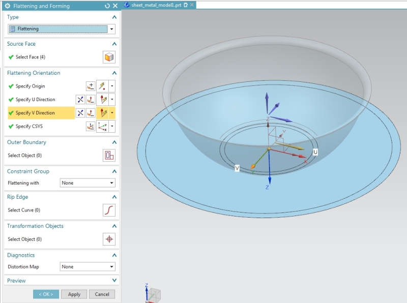
Another option is the flattening and forming tool added to modeling in NX11 (and improved in NX12) that will create a literal surface flatten (no distortion). Have a look here for a quick demo Flattening and Forming in NX12
2018-01-29_08_31_06-Siemens_NX_-_Modeling_jmpxq5.jpg


Both methods produce a slightly different result and of course would be affected by material properties. There is another option - analyze formability - one step where you can define material properties.

On the part I created to experiment I got the following results:
Sheet Metal Flat Solid - ~50mm DIA
Modeling Flattening and Forming - 46.8mm DIA
Analyze One Step - 47.1 DIA

Select the method that best suits your process.
 
deedub777, did you try my 'mathematical' method as a comparison?

John R. Baker, P.E. (ret)
EX-Product 'Evangelist'
Irvine, CA
Siemens PLM:
UG/NX Museum:

The secret of life is not finding someone to live with
It's finding someone you can't live without
 
JohnRBaker said:
deedub777, did you try my 'mathematical' method as a comparison?
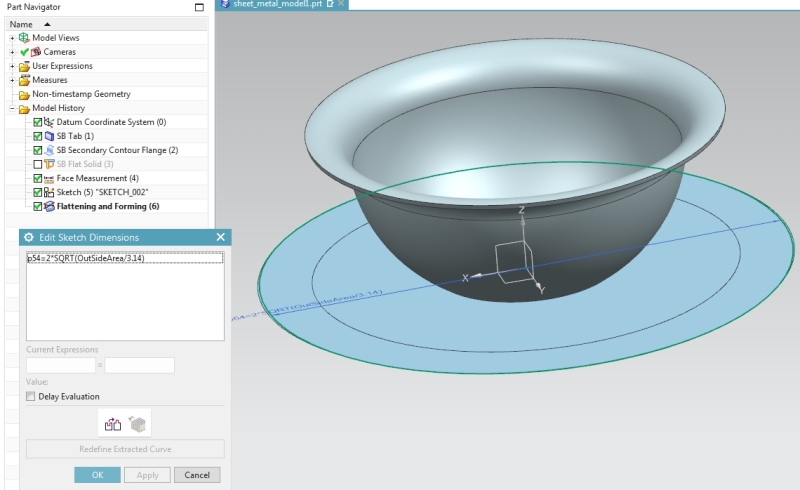
I didn't save the part however did a quick re-run and found the mathematical approach was extremely close to the flattening and forming result (without fixed elements)
2018-01-30_11_49_01-Siemens_NX_-_Sheet_Metal_bzfbrt.jpg
 
Status
Not open for further replies.

Part and Inventory Search

Sponsor