Eng-Tips is the largest engineering community on the Internet

Intelligent Work Forums for Engineering Professionals

  • Congratulations waross on being selected by the Tek-Tips community for having the most helpful posts in the forums last week. Way to Go!

NX Advanced Simulation - Beam deflection 1

Status
Not open for further replies.

4udoudo

Structural
Aug 25, 2014
7
0
0
PL
Hello All!

In a simple calculation of a beam under uniformly distributed load I have got two times bigger value of deflection than expected (hand-made). At the same time the situation with values of reactions, bending moments and stresses looks OK.

I would be grateful if somebody point - what is made wrong in my calculations (explanatory pictures and the model files are attached).

Thank you in advance.
 
Replies continue below

Recommended for you

The textbook formula you have is for Pinned-Pinned Beam. In the NX model, you have one end with TX, TY, TZ and RX constrained, basically pinned in the XZ plane, which is fine. At the other end you have TY and TZ constrained, but TX is free, therefore your beam is free to slide at this end in the X direction, different from the textbook formula for a Pinned Pinned beam where TX is constrained.
 
Thank you for the reply.

Yes, a roller/slider is not shown below one of the supports on this picture, but the value below it are calculated correctly as for a 'classical' simply supported beam.

It can be checked by the following calculation:
==========
Beam length: L = 1.00 m
UDL : q = 200 kN
Young's modulus : E = 2.06E+08 kN/m[sup]2[/sup]
Moment of inertia : J = 7.62E-05 m[sup]4[/sup]

w max = (5/384) * (q * L^4) / (E * J)
w max = (5/384) * (200 * 1.00^4) / (2.06E+08 * 7.62E-05)
w max = 0.0001659 m = 0.166 mm

==========
or by using one of online calculators (e.g. here or here)

So I still do not understand where a mistake is.
 
I have tried with simple rectangular and rod cross sections, the answer between simulation and hand calculation are coincided. Your hand calculation is correct. This make me think that there is something in NX cross section that I have not figure it out, for example, the interpretation of displacement result is not based on the centroid location of the cross section? However, your current 1D result does coincide to a 3D I beam result i built, max deflection is 0.321mm.
 
Hello!,
I have investigated the problem and this is something related with the shear stiffness factors K1 and K2 in the PBEAM card of NX NASTRAN that adjust the effective transverse shear cross-section area according to the Timoshenko Beam Theory. By default NX NASTRAN follows the Timoshenko Beam Theory icluding the effects of shear deformation. To neglect shear deformation (i.e., to obtain the Bernoulli-Euler Beam Theory), the values of K1 and K2 should be set to 0.0.

In fact, I have replicated the problem in FEMAP solving with NX NASTRAN 9.1 and I get similar results as you using the default values with maximum displacement in the center = 0.32361 mm, here you are:

timoshenko-beam-theory1.png


Here you are the values of the beam cross section used:

cross-section-shear-factor-default-pbeaml.png
cross-section-pbeaml.png


If now I edit the beam cross section properties and enter 0.0 for the shear area factors in FEMAP (please note "Shear area factor = K shear stiffness / area") then this will neglect shear deformation and will make that NX NASTRAN to use the Bernoulli-Euler Beam Theory. In fact, the maximum displacement now is 0.16865 mm, in agreement with the hand calculations.

zero-shear-stiffness.png


bernoulli-euler_beam_theory.png


SUMMARY
The Euler–Bernoulli beam theory (also known as engineer's beam theory or classical beam theory) is a simplification of the linear theory of elasticity which provides a means of calculating the load-carrying and deflection characteristics of beams. It covers the case for small deflections of a beam that is subjected to lateral loads only. It is thus a special case of Timoshenko beam theory that accounts for shear deformation and is applicable for thick beams.

Things to learn: the beam theory has many, many limitations, please use it with caution, do not get confused. Also for those using thin walled (and open!!) beam cross sections I strongly suggest to forget at all the beam elements and mesh with 2-D Shell CQUAD4 elements, if obtaining accurate results is what you want, OK?.

Best regards,
Blas.

~~~~~~~~~~~~~~~~~~~~~~
Blas Molero Hidalgo
Ingeniero Industrial
Director

IBERISA
48004 BILBAO (SPAIN)
WEB: Blog de FEMAP & NX Nastran:
 
Hi Blas,

Thanks for pointing out the problem! I am pretty sure that no user interface is found in NX to toggle the parameter except for direct keyword editting.
For keyword editting procedure, in NX, click on solve, but choose Write, Edit & Solve Input File, then OK.
30b2sd1.jpg


Scroll until the PBEAM keyword
234ln5.jpg


Change the K1 and K2 value to 0.0 (Please take note 0.0 is a number format and is required here, instead of 0)
34i1qxc.jpg


Save the file and exit, the solver will run then.

 
Dear Tuw,
In the modern interface of NX AdvSim 9.0 this is only possible if the user EDIT THE BEAM COLLECTOR in the FEM environment and changes the type of beam property from PBEAML to PBEAM. And for novice users editing the NASTRAN input deck is quite cumbersone, always subjected to syntax error, then my suggestion is to use the following method:
1.- Go to FEM environment and edit the Beam Collector.
2.- Change the TYPE from PBEAML to PBEAM.
The 
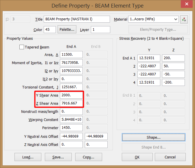
PBEAM entry allows the user to enter the cross-sectional properties of the beam (such as area, moments of inertia, shear center, etc.). The PBEAML entry, in contrast, lets you input a number of common cross-section types such as bar, box, I-beam, channel, and angle sections by their dimensions instead of by their section properties. For example, you can define a rectangular cross section by its height and depth rather than the area or moments of inertia. But with PBEAML card the nastran input deck contains only the dimensions of the cross section, not the cross section properties data, then not possible to enter the K1 and K2 values, understood?.

3.- Under BEAM PROPERTY click on CREATE PHYSICAL.

edit2.png


4.- In the FORE SECTION of the PBEAM form click on SHOW SECTION MANAGER (do not forget to select a material!!). In the following form click on CREATE SECTION.

edit3.png
edit4.png


5.- In the new BEAM SECTION choose the option USER DEFINED and doing copy & paste copy the cross sectional properties of the previous beam cross section. Basically for computing displacements you need AREA and Izz. Also enter 0.0 in the fields of SHEAR STIFFNESS FACTOR K1 & K2, their default values of 1.0 approximate the effects of shear deformation. To neglect shear deformation (i.e., to obtain the Bernoulli-Euler beam theory), the values of K1 and K2 should be set to 0.0.

edit5.png


Save and solve and you will see & postprocess the new results, coincident with "horrible" hand-made calculations, OK?.

final-result.png


Best regards,
Blas.

~~~~~~~~~~~~~~~~~~~~~~
Blas Molero Hidalgo
Ingeniero Industrial
Director

IBERISA
48004 BILBAO (SPAIN)
WEB: Blog de FEMAP & NX Nastran:
 
Blas, thank you very much for the clarification of the problem. :)

Tuw and mrfemap, thank you as well.

I think that although the variant with the ‘surgical’ nullification proposed by Tuw is a little bit risky it looks very practicable because of being realized accurately it gives us ability to observe distribution of stresses along the cross-sections using command Beam Cross Section View. In the variant with ‘legal’ assignment of User Defined Properties this function will be unavailable.
 
Dear 4udoudo,
The message is clear: Your first model is perfect, no need to make any modification on the Shear stiffness factor, the beam results obtained using FINITE ELEMENT ANALYSIS (please note I say any FEA, not only NX NASTRAN) are correct, they give you the maximum accurate results, forgot to use the "hand-made" classical beam theory because it has many limitations, OK?.

The "complex" explanation given above is for you to understand the problem posed, why we have discrepancy between hand-made calculations and FEA results, but do not let to use FEA results, they are the most accurate possible. Please note BEAM END MAX COMBINED STRESS RESULTS are the same using Timoshenko or Euler-Bernoulli Beam Theory: using the classical beam theory the beam structure is stiffer than in real life!!, so caution .., be critical.

And finally, do not get totally happy with beam FEA results, make a double-check using Shell 2-D CQUAD4 elements, beam elements are for a "global" study of the problem only, but Shell elements give you precious "local" information of both stiffness & stresses and displacements, OK?.
Best regards,
Blas.


~~~~~~~~~~~~~~~~~~~~~~
Blas Molero Hidalgo
Ingeniero Industrial
Director

IBERISA
48004 BILBAO (SPAIN)
WEB: Blog de FEMAP & NX Nastran:
 
Status
Not open for further replies.
Back
Top