Continue to Site

Eng-Tips is the largest engineering community on the Internet

Intelligent Work Forums for Engineering Professionals

  • Congratulations KootK on being selected by the Eng-Tips community for having the most helpful posts in the forums last week. Way to Go!

NX NASTRAN mesh 3d 3

Status
Not open for further replies.

ecto1000

Mechanical
Oct 12, 2023
13
Hi everyone,

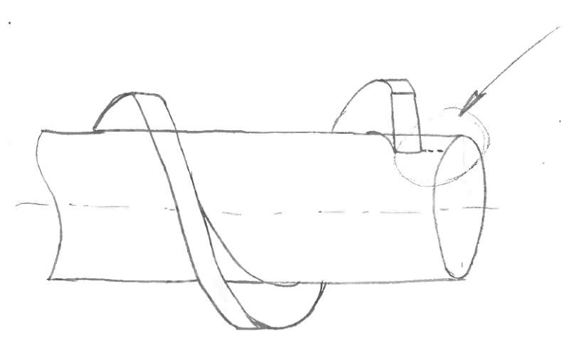
I would like to perform a FEM with NX NASTRAN of this propeller on the shaft. The shaft is about 300 mm in Dia. while the propeller section is 50 x 150.
My question is about 3d mesh. If I do it with just the helix (for another type of calculation) it works very well: first I do the 2d on the starting and end section, and then the extruded 3d (with QUAD elements).
If, however, I dedicate myself to the assembly with the shaft, it happens that I am unable to create the 2D mesh of the two lateral surfaces of the propeller and I get a surface (which I interpret to be degenerate, basically a line) in the highlighted area. I have represented the line as dotted. So the 3d mesh also fails.
I don't have fillets, but I tried with fillets too.

Thanks to anyone who can give me advice!
62261-8876ae3e10e17734aa9697f4ab3e1c9e_dwhpjo.png
 
Replies continue below

Recommended for you

you should be able to mesh the shaft, without the spline, and embed the common nodes from the spline into the shaft mesh.

"Hoffen wir mal, dass alles gut geht !"
General Paulus, Nov 1942, outside Stalingrad after the launch of Operation Uranus.
 
So, in the same fem model, you're suggesting to 2d mesh firstly the shaft, and after that 2d mesh the propeller.
Right?
If I misunderstood please be patient and say to me in details [wink]
 
actually I said it the other way around (since you said you could mesh the involute).

mesh the involute, 3D mesh right (solid elements) ?

then you'll have a set of nodes on the inner surface of the involute, the outer surface of the shaft.
embed these nodes onto the shaft surface, mesh the shaft (3D elements, no?).

"Hoffen wir mal, dass alles gut geht !"
General Paulus, Nov 1942, outside Stalingrad after the launch of Operation Uranus.
 
I see. Yes I could mesh the helix alone, but I mean, when it is in a separate 3d file, without the shaft.
But I got your point.
Anyway, I found the cause of my issue.
I was working on a 3d coming from a .step file done by another person, I forgot to mention this, my fault sorry.
So after reproducing the same 3d in NX I can succesfully 2d mesh it with QUADS, I'm working on 3d mesh with quads, but 3d extrusion doesn't find a path so I think I'll go for TRIA.
Thanks
 
Many FEA packages and codes support Bonded contact (or sometimes it is called mesh gluing). With this contact type you can mesh separately shaft and helix using brick mesh and then connect two nonconformal meshes using contact. Like "glue" two meshes together.
 
Thank you very much for your suggestion.
I will give it a try.
But some questions are arising in my head.
If, like in this case, I'm dealing with a prt made by two solids (or more), do I have to make one single solid out of the two ones, before meshing?
Or is it not necessary?
Which is the usual procedure you follow?
Having a single solid will help the mesher to make a 3d conformal mesh?
I understood that glueing is a way, but I think it is not so good for high stress gradient areas (or for the areas of interest in the calculation).
Correct me if I am wrong, of course!
Thanks
 
If you don`t limited on computer resources than you can merge all geometry into one solid body and mesh it with tetrahedral elements. Use smaller mesh size in regions with high stress gradients. Don`t forget to enable midside nodes for tetrahedral elements it is critical.
 
Ok!
I was more focused in Hexa since I remember that they work smarter.
What do you suggest as procedure for them?
Just for my learning.
Thanks
 
Don`t think that all hexa mesh is possible for this geometry. If you revolve mesh for screw and shaft than you get some distorted mesh near shaft axis.
Maybe you can get all hexa mesh using mesh glueing. Revolve helix and some part of shaft and extrude central part of shaft and glue them together. Now you should somehow make end portion of shaft. Maybe you can first create all those shaft components in 3D geometry and using boolean operations you get geometry of missing part. It will look like ring and you can mesh in bu extrusion in radial direction.
12345_uwveur.png
 
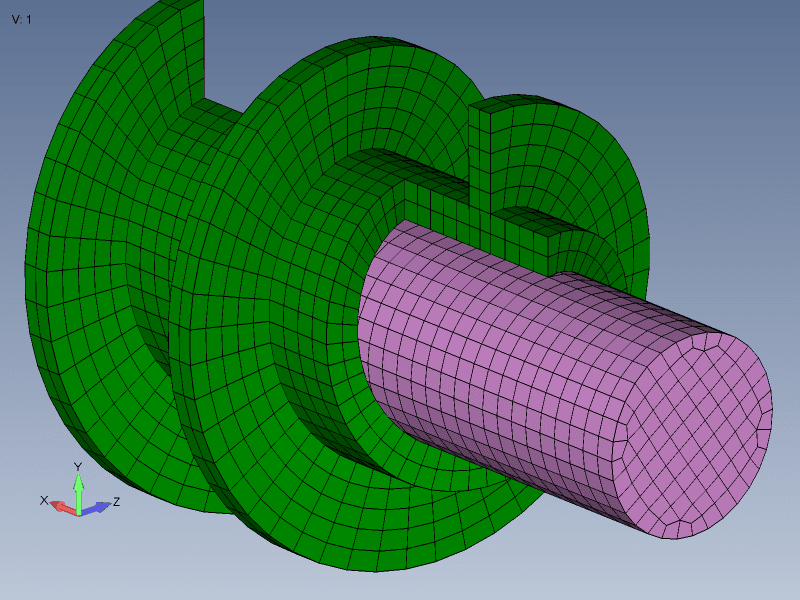
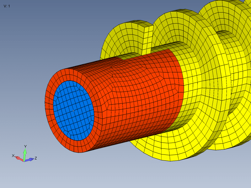
Your problem interested me. I made a complete grid. Here red and yellow mesh has common nodes - it is conformal mesh. This outer mesh should be glued to the blue core mesh. You can make central part even more tiny to move glue interface further away from region of interest. I made this mesh in Femap and made CAD geometry in Solidworks. If you use NX than you should figure how to do it by your own. this may require some CAD operations prior to meshing. I can upload mesh and CAD geometry if needed.
123_d6hk0k.png
 
To the OP, the meshing is just one issue. But what is the purpose of the FEM? How are you going to load the part? And use what boundary conditions?
 
Uao, good idea. Yes please upload everything. Thanks
I will apply different combinations of axial load and torque.
 
Ok thanks a lot.
But the difference between Femap and Nx Nastran isn't so clear to me.
I've got Nx10, but not Femap.
So I think I can't do the revolving mesh operation you described?
Is Femap a separate software right?
 
Yes, Femap is separate software. Both Femap and NX use Nastran solver to perform finite element calculations.

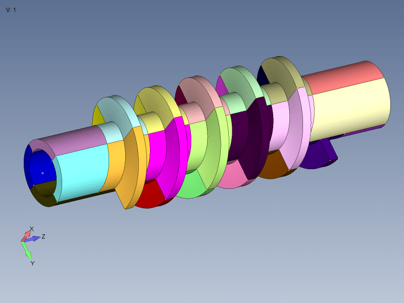
As for your problem, here is one solution that comes to my mind. Revolve geometry into small part of helix. Let`s say 90 degree portion. Than copy this part with rotation to make complete helix. Now you have many small parts that can be hex meshed as 3D body. Here on picture I make each 3D part with different color so you get what I mean.
It is possible that it will be easier to recreate model 3D geometry in some CAD software from scratch than modifying existing shaft geometry.
3D_geometry_iwyoew.png
 
how are you building the model ? NX is the analysis engine. These days everyone uses some s/ware to help build the model (FeMap, PATRAN, etc). Back in the day you used pencil and paper !

"Hoffen wir mal, dass alles gut geht !"
General Paulus, Nov 1942, outside Stalingrad after the launch of Operation Uranus.
 
Status
Not open for further replies.

Part and Inventory Search

Sponsor