Continue to Site

Eng-Tips is the largest engineering community on the Internet

Intelligent Work Forums for Engineering Professionals

  • Congratulations SDETERS on being selected by the Eng-Tips community for having the most helpful posts in the forums last week. Way to Go!

NX Nastran - Rotation won't be fixed

Status
Not open for further replies.

Suncad

Mechanical
Oct 30, 2013
44
Hi there,
I have a problem for a couple of days on NX12 Simulation, using NASTRAN solver. I am unable to lock rotation of a face while applying displacement or force over one axis. Whether I use "user-defined constraint" or "fix all rotations", on the face I want to constraint, it just won't. My model is similar to a tube with two flanges, one at each side. Here is a draft of the simulation :
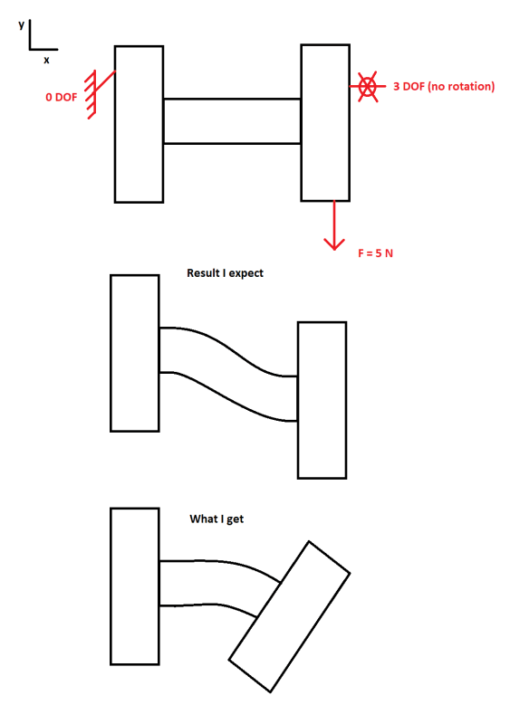
Sans_titre_pdjxy4.png

It is like NX is considering rotation lock at element local CSYS level.
I do get what I expect using a slider constraint (along Y), but slider also lock X which I don't want to be lock. I tried a bunch of solution, bc, but it always behave the same.
When I look to results, I do have a gradient of x displacement on the loaded face, but if I plot rotation around z, I have 0 on the entire model. How is that even possible ?
 
Replies continue below

Recommended for you

Soild elements only have 3 DOFs per node, they only support translational DOFs.
 
Thanks,

I have worked this out a little bit and your are right. I understand 3D volume meshed with SOLID elements (like CTETRA or SOLID187) have only 3 DOF elements (ux,uy,uz). Is there a way to achieve the behavour I expected first with some tweaking ?
 
Hello!,
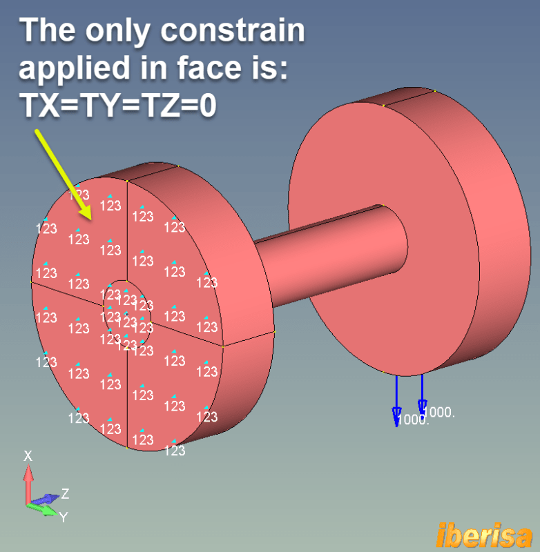
Simply apply the external constraint TX=0 on ALL the nodes of the face and you are done, this is the way to apply a FOLLOWER FORCE.
Best regards,
Blas.

~~~~~~~~~~~~~~~~~~~~~~
Blas Molero Hidalgo
Ingeniero Industrial
Director

IBERISA
48004 BILBAO (SPAIN)
WEB: Blog de FEMAP & NX Nastran:
 
Constraining in X is so obvious I'd assumed the OP's problem was more complex, i.e. the face is free to move in X but must remain parallel to the fixed face.
 
Hello!,
No problem, all is dependent of what the end user wants do to.
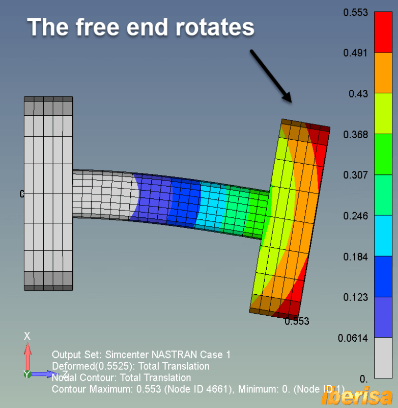
In fact, if I simply constraint the left face and apply a vertical load at the opposite free end face the model rotates.
This is the starting point:

eje-blas1_povjco.png


And this is the solution of simply linear static analysis using Simcenter Nastran (SOL101):

eje-blas2_tnxqan.png


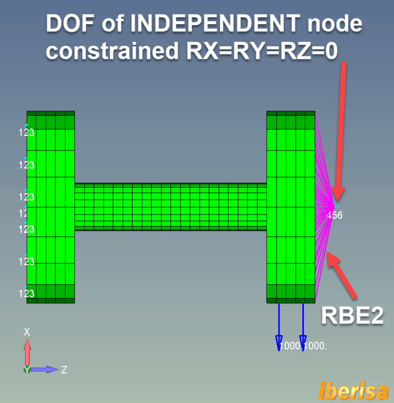
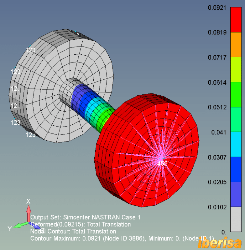
If the requirement is the right free end not rotation at all and NOT VALID to constrain the axial displacement (TZ=0) then the trick is very simple: 3-D Solid elements do not have rotational DOF, yes, then is useless to constrain rotations. But you can create a simply rigid RBE2 element using all the nodes of the right free face and constraint the rotational DOF of the INDEPENDENT node, and you are done!!

This is the starting point of FEA model REV1: only rotational DOF of independent node are prescribed (really simply RY=0 is enough)

eje-blas-rev1-1_g9ky0f.png


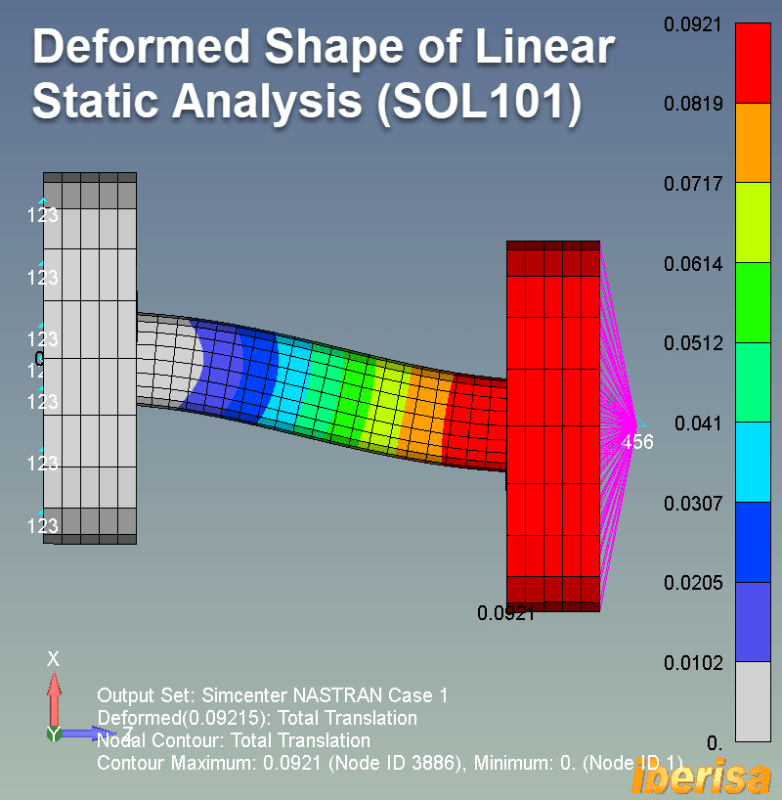
And this is the deformed shape of the linear static analysis with Simcenter Nastran (SOL101):

eje-blas-rev1-2_i5xubi.png

eje-blas-rev1-3_ohjeje.png


Best regards,
Blas.

~~~~~~~~~~~~~~~~~~~~~~
Blas Molero Hidalgo
Ingeniero Industrial
Director

IBERISA
48004 BILBAO (SPAIN)
WEB: Blog de FEMAP & NX Nastran:
 
Thta's excellent Blas. I'd thought of using RBE2s or maybe a skin of shell elements on the end face but wasn't sure how.
 
Status
Not open for further replies.

Part and Inventory Search

Sponsor