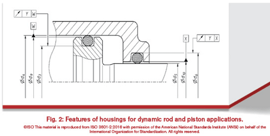
The runout tolerances in that ISO figure would be a step towards what could be used. With no envelope modifiers (circle E) and no coaxiality controls for the larger and smaller diameter features within each of the two parts, no worst-case boundaries can be found, so the o-ring squeeze range cannot be determined. It also seems odd to me that clearance features are chosen as datum features for both parts. If the inner part moves to the left relative to the outer part a sufficient amount then coaxiality of d5 and the o-ring groove on the inner part (and similar for the outer part) becomes less significant, but what about when the inner part is shifted fully to the right relative to the outer part? Coaxiality of the larger and smaller features on each part then becomes a concern for o-ring squeeze.
Wouldn't it be better to specify d5 as datum feature W and d4 as datum feature X (and also rename "X" to use a better letter, to avoid using X, Y or Z as a datum feature letter)?
With what I think are better choices for datum features along with a combination of size, to control size and form (using ASME Y14.5), and position applied at RFS, to control location and orientation of each o-ring groove cylindrical surface, and also the clearance features then worst case boundaries (I wish we could call them the MMB for each of the features) could easily be determined. From those boundaries the range of o-ring squeeze can easily be determined.
Size and runout tolerances or profile tolerances, as has been pointed out already, could be used too, as long as coaxiality of the cylindrical features within each of the two parts is included.
Another point is that these part may be manufactured by a process other than machining, such as injection molding or 3D printing. Whether a machinist can likely make things good enough doesn't always mean that ambiguous or incomplete tolerances will mitigate risk well enough.
Oh, and Happy Easter to all
")
Dean Watts