Eng-Tips is the largest engineering community on the Internet

Intelligent Work Forums for Engineering Professionals

  • Congratulations waross on being selected by the Tek-Tips community for having the most helpful posts in the forums last week. Way to Go!

Odd Baldor inverter duty two speed motor with two windings 3

Status
Not open for further replies.

edison123

Electrical
Oct 23, 2002
4,409
0
0
IN
The motor nameplate

IMG_8163_h2o0au.jpg


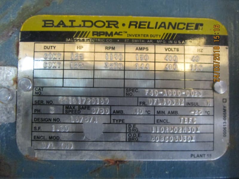
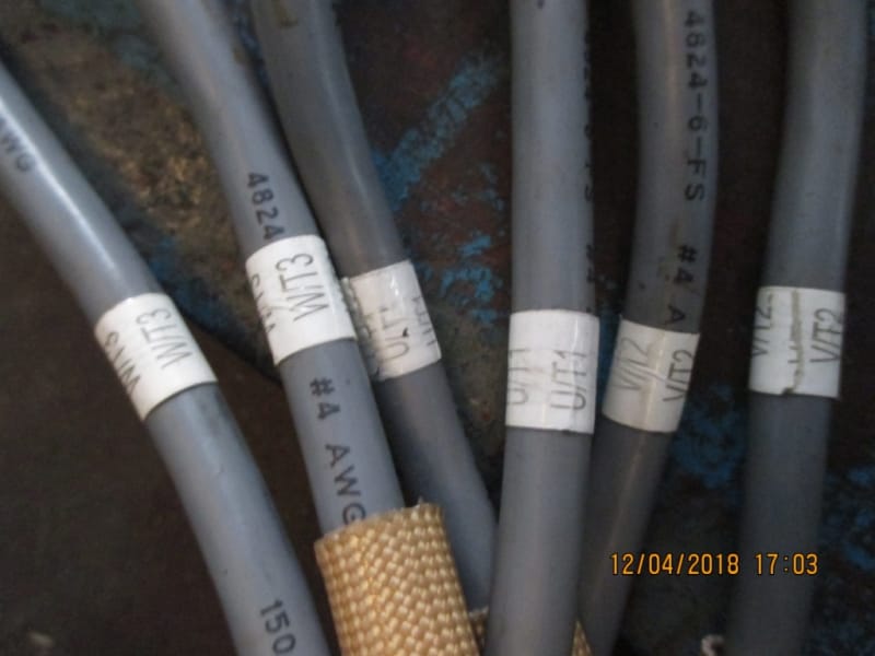
From the nameplate, it is clear both the speeds of 1190 RPM/40 Hz & 3270 RPM/110 Hz are coming from the same base speed of 1500 RPM, 50 Hz. And yet, the motor has two different windings (Total 6 leads. One batch of 3 leads marked as T1, T2, T3 have no continuity to the other batch of 3 leads also marked as T1, T2, T3) and both windings are wound for the same base speed of 1500 RPM.

Why two windings with the same base speed? Absence of any connection diagram on the motor nameplate makes it more confusing. Are both windings supposed to be connected together to the VFD?

Also, since it is a VFD driven motor, then why only two speeds? Why not the entire range from 40 Hz to 110 Hz?

Muthu
 
Replies continue below

Recommended for you

Notice that the voltage remains the same. Different V/Hz ratios for the different windings. That way you can run at 110Hz without having to increase the voltage.


" We are all here on earth to help others; what on earth the others are here for I don't know." -- W. H. Auden
 
Thanks Jeff. That makes sense now. So, one has to connect the VFD to one winding for speeds up to 1190 RPM and then switch the VFD to the other winding for speeds up to 3270 RPM? Is this type of switching windings done automatically by the VFD itself?

Muthu
 
The other possibility is that there are two parallel windings meant to be always connected together.


Bill
--------------------
"Why not the best?"
Jimmy Carter
 
Muthu,
Switching of which windings are used would have to be done externally, either by a set of mechanically interlocked contactors (the same as any 2 speed 2 winding motor) or with a manual changeover switch. You would also need interlocking to ensure that the VFD output is disabled before switching.


" We are all here on earth to help others; what on earth the others are here for I don't know." -- W. H. Auden
 
But;
1190 RPM plus 10 RPM slip = 1200 RPM @ 40 Hz, or 30 RPM per Hz.
3270 RPM plus 30 RPM slip = 3300 RPM @ 110 Hz or 30 RPM per Hz.
Any standard for motor connections that I have ever seen would use different numbers for the second winding.
I have seen motors with twin leads; Two T1's, two T2's, Two T3's. The leads were connected together to the windings and in the terminal box.
This looks like full HP over a turn down range of 3:1
How about a base motor at 60 Hz and 1800 RPM. That would give 1200 at 40 Hz. and 3300 RPM at 110 Hz.
But you are probably correct that this is a re-rated 50 Hz motor.
How about a 50 Hz motor with a service factor of 1.25? That would give a 125 HP motor a usable 156 HP at 50 Hz.
This would derate to 125 HP at 40 Hz.
I strongly suspect that to save space, rather than a connection of two parallel windings and two leads, the motor was built with two identical windings with a lead from each winding to the terminal box.
Take a look at the size of the leads, Muthu. In your best judgement are the leads suitable for the rated 150 Amps or are the leads more suited to 75 Amps each?
Will you be able to test run the motor?

Bill
--------------------
"Why not the best?"
Jimmy Carter
 
Thanks Jeff and Bill.

Today, we will be measuring the DC resistances of both the windings. Then, run them in open shaft condition with each winding separately energized and note the currents & speeds followed by combined winding energization run. Of course, this can be done only at 50 Hz.

If you look at V/Hz, the one at 3270 RPM is way too low. Wouldn't that affect the motor torque severely since it reduces the flux? I am still trying to get the logic behind this rating.

The cables are marked #4 AWG which is around 100 sq mm?

IMG_3630_g6bvqb.jpg


Muthu
 
The line to line (T1 to T2, T2 to T3 etc.) DC resistance of each winding was same at 65 mΩ at 32 deg C. So, both the windings seem to be identical.

But during no load test, both the windings went into saturation very early and the speed was only 1000 RPM at 50 Hz (with the same direction of rotation for both the windings).

Open shaft test results
115 V - 85 A - 1000 RPM
120 V - 97 A - 1000 RPM
150 V - 150 A (which is already the rated load current) - 1000 RPM

During this no load test, only one winding was energized while the other was kept open.

We never got to the rated 400 V. Even assuming the windings are designed for 400V/110 Hz, the no load current is already hitting the full load current before even reaching 181 V, 50 Hz (V/Hz ratio). And the speed stabilized at 1000 RPM, not even close to the rated 3270 RPM. The motor turns freely by hand thus ruling out stuck rotor or cocked bearings.

Something is screwed up with these windings and/or the nameplate.

We are dismantling the motor to have a looksee at the windings themselves.


Muthu
 
50 Hz / 110 Hz = 0.455
400 Volts x 0.455 = 182 Volts.
Try 182 Volts at 50 Hz.
I suspect that 400 Volts @ 40 Hz on the nameplate is the error.
How do the winding resistances compare? (T1 to T@, not T1 to ground)

Bill
--------------------
"Why not the best?"
Jimmy Carter
 
Muthu
Thank you for your kind reply. I missed that.
I'll be interested to hear if the windings are star or delta connected.
Guess. If the windings were replaced and then connected in delta rather than in star, my previous suggestion would make more sense.
Waiting to hear.
Yours
Bill

Bill
--------------------
"Why not the best?"
Jimmy Carter
 
I would suspect this to be parrallel (2)1's,2)2's,2)3's)leads due to lack of room in bearing housing for large leads and also maneuvering large leads through rear housing when installing or removing rear housing. Although your no load test data doesn't show this, but Performance data shows motor with 460 volts @ 40hz should pull 61 amps. You may have only applied power to half or part of the winding if only applied to 3 of the 6 leads.
 
Edison123,

This motor is equipped with parallel windings that are not internally connected but must be connected in the terminal box to complete the circuit.

With regard to rating, this is a special type of variable speed motor that is designed for inverter use only. It is considered to be an optimum pole design (ie. base speed is not at 50/60hz) and is meant to emulate DC motor performance. Like a DC motor, the rating includes a base speed and a constant horsepower speed.

Below base speed the motor is in the constant torque speed range and it operates in typical V/Hz mode (ie. 400V/40Hz, 300V/30Hz, 200V/20Hz, etc). Above base speed the motor is in the constant horsepower speed range and the voltage remains fixed while the frequency increases (field weakening - 400V/40Hz, 400V/50Hz, 400V/60Hz, etc.).

Let me know if you need additional technical support.

 
Thanks Ray. I have also replied to your mail.

We opened the motor and gave 50 V, 50 Hz supply to each winding with a current of 63 Amps.

To my surprise, we found one winding was physically spread over from 12 O’clock to 6 O’clock position while the other was spread from 6 O’clock and 12 O’clock.

The magnetic needle was spinning only in one half of the periphery depending on which winding was energized. Also, only the energized portion of the winding was getting warmer while the other half stayed cold confirming the bifurcation of the winding.

Then both the windings were linked and energized at 50 V, 50 Hz with a current of 108 Amps and the needle was spinning all around the periphery.

We reassembled and energized both the windings together at 400 V, 50 Hz. The no load current was 37 Amps and the speed was the rated 1500 RPM.

First time I have come across such a split winding with each winding covering only one half of the periphery.

Any particular reason for this design?

Also, at 3270 RPM, given the drastic reduction of V/Hz, won’t the torque also be reduced significantly?


Muthu
 
Thanks for the update Muthu.
Did I understand that correctly, that the current drops when both windings are energized? Very interesting,- strange but interesting.

Bill
--------------------
"Why not the best?"
Jimmy Carter
 
Yes, Bill. Counter intuitively, the current dropped when the two windings were connected in parallel because I guess since the winding is complete when only both the sections are connected, the incomplete windings behave in strange ways.

Muthu
 
Muthu,

The winding is a conventional two circuit - four pole design but the long jumpers between the two circuits are not used because, given the use of parallel leads, they are unnecessary. It is no more complicated than that.

You are correct, the motor torque decreases above base speed as the V/Hz ratio decreases. Keep in mind that this is a purpose built variable speed motor that is most likely in an application that previously would have required a wide speed range DC motor.

When comparing AC motor performance to DC motor performance, V/Hz ~ flux ~ torque in an AC motor and field excitation ~ flux ~ torque in a DC motor. For both types of machine the flux is constant below base speed as is the torque capability. Also, for both types of machine the flux is reduced above base speed resulting in reduced torque but constant power as speed increases.

Thus, this type of motor can be used as a direct replacement for a DC machine having the same rating and will provide the same performance envelope without the requirement of maintaining the commutator and brushes.

 
Thanks Ray. The client bought this motor as a package for a rubber mill. Hopefully, the high speed operation has been designed for that kind of load.

Since this is an inverter duty motor, I do not understand the concept behind splitting the winding since such splits are normally used for part winding start large motors to reduce the inrush current. Since this is only a 125 HP motor, wouldn’t a regular winding have been suffice, especially with a VFD drive?

Thanks once again for your kind inputs.


Muthu
 
Muthu,

This motor is a custom design and it is too old to show up in the computer. I have requested the specification/design information from the factory and will let you know what I find. Otherwise, I will say with confidence that the motor will meet the requirements of a rubber mill if the client specified it properly for that application.

With regard to the winding, a 'regular' winding, one in which the parallel circuits are internally connected, would be suitable for type of motor, However, the internal connection is superfluous when each winding has it's own set of externally connected leads. This is simply a manufacturing expedient and a cost savings, there is no technical reason for the split. Having said that, there is no loss in performance for this type of design, it is electrically equivalent to an internally connected winding with a single set of leads.
 
Status
Not open for further replies.
Back
Top