Continue to Site

Eng-Tips is the largest engineering community on the Internet

Intelligent Work Forums for Engineering Professionals

  • Congratulations SSS148 on being selected by the Eng-Tips community for having the most helpful posts in the forums last week. Way to Go!

Off-road Long Travel Suspension 1

Status
Not open for further replies.

GEspo

Automotive
Aug 25, 2020
90
Hello eng-tips experts. For starters: I have a complete, fairly high fidelity, RBD simulation model of an off-road race vehicle, in Maplesim. Currently the model sits with IFS and a rear 4-link, triple bypass and dual rate coilovers on ea corner, real Modelon fluid flows. After a month or so working with the completed model, it's apparent the usual(pavement) race car dynamics analysis will only go so far due to the low coefficient of friction, ie dirt and tire, looks to be about .6, so lateral g's are restricted, and lots of sliding happens, just watch any race etc... SO to my question: Turning my focus to BUMP characteristics and analysis, are there any good resources that layout the study of long travel suspensions? Seems like studying a slinky would be more helpful than opening a dynamics book(I've opened a few btw)..

(As a guide, I'll generalize and define "long travel suspension" as a VERY Soft system with anywhere from 20" to 30" of travel..)
 
Replies continue below

Recommended for you

Going through a few models and testing the Z_r formula above, I notice for awd and front wheel drive the antisquat formulas presented above(for rwd) don't apply..
 
... Do you understand why?

And do you understand why there's a difference between a live-rear-axle rear-drive vehicle, and an independent-suspension rear-drive vehicle?

It is possible to have some anti-squat with independent suspension designs (in which the drive torque for the rear wheels has reaction forces directly to the sprung-mass chassis as opposed to the unsprung axle in which those reaction forces pass through the axle-guiding-and-locating mechanism) ... but there are considerable side-effects that are mostly bad, so it normally isn't done to any significant extent.

And if you have a typical independent-suspension vehicle with the drive going through CV-jointed shafts to the wheels with the brakes at the wheel hubs, anti-squat (acceleration) is different from anti-dive (braking).
 
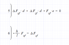
I'm evaluating my 1) formula above and it needs to be noted that F_x is F_xr, for rear axle. Shown below are another few eqn to add to this for trivial suspensions. Eqn 1) above and 5) here are equilibrium about the pivot. F_x acting on the driven axle, I should mention..

Screen_shot_2020-12-30_at_11.17.48_AM_kmzvnu.png


I haven't ventured into ifs/irs quite yet, however the trivial designs are fairly close in form but would be acting in a longitudinal direction vs lateral(if that makes sense).. like the entire vehicle suspension is a single independent(like one of the pics above).. I'm hoping to use that concept to explore what's happening in lateral(turn), where I'll switch to ifs/irs, and eventually the goal of ifs w/ rear solid... thanks for the posts!
 
Thanks everyone for bearing with me on this adventure... SO I have yet another basic question as I jump into lateral dynamics...

F_x creates a rolling tire
F_y acts somewhat perpendicular(at the side of the tire) through slip(angle etc) to "push" the rolling tire

If I tested pushing a stationary vehicle to gain insight on F_y, how much different(mathematically) would that be than to push an already rolling tire?

 
So you are looking at a slip angle of 90 degrees. If you look at a typical friction plot for a tire you'll see it is roughly circular, but modern tires are specifically developed to give squarer circles, and the ratio of max fx/max fy is actually something we'd like to see increased (that is the ability to brake the vehicle is more important than the ability to make it roll).

is an example

Cheers

Greg Locock


New here? Try reading these, they might help FAQ731-376
 
Great info on the friction circles, much appreciated.

Wrapping up longitudinal I wanted to address differences in awd and fwd/rwd: when considering Fx acting on the com and axles, for awd we see the relationship Fx_f (fx on front axle) and Fx_r as

Fx_f + Fx_r = Fx_com

From empirical studies Fx_f(or Fx_r) and Fx_com exhibit a non linear relationship, and can be modeled by a quadratic, dependent on Fx or applied Forces.. so to attempt to restrict the forces going through the suspension its not totally clear, as in the case for rwd above where setting e/d = h/l will result in no spring compression, ie no change in Fs.

Noted here is one method that seems interesting: if you take the max of the quadratic you'll end up with some value that is the most force that can possibly go through the axle in relation to force acting on the com given h,l and mass etc (you can find max Fx from coeff of friction * Fz etc) so we are looking at max Fx_f in relation to Fx_com.. then we use max Fx_f(I will not include the math here) in some way to minimize(better control) the forces, ie setting e/d = h/l, except you get something like e/d = (h/ (1/2 - 2h/(l-h))) as one example(this would change depending on inputs)... which is dependent on Fx, so at some Fx there will be 0 forces acting on the susp, if solved for appropriately. As far as the rest of possible Fx this method seems to provide good control throughout the range, and can be used for rear and front.

As I stated above there wont be math posted for this since its largely empirical and based on given inputs so doesn't easily generalize, not to mention there are many approaches once you decide on a function(quadratic, log etc)..

Time has been spent analyzing awd in the hopes it will relate to lateral since we have forces acting on both axles in these cases..


Currently doing lots of model testing of lateral forces. I'd like to get confirmation on what happens to Fx when steering is applied(awd or any drive mthd) in ACCEL, transient state:

At turn initiation(steering is applied) Fx on inside tires increases, and outside tires become negative(not decreases but negative, ie forces opposing the wheel direction)? If we consider loading, wouldn't we have something of the opposite, since in straight line(longitudinal) accel Fx_rear > Fx_front... also in the case of loading we are still positive. The negative Fx outside appears to be dependent on track width, so the wider the more negative, becoming less negative and eventually positive/switching(inside becomes negative) with a very narrow track..

(I've tried a few different models, one with a moment at the com vs steering, one with pushing wheels vs creating torque (trying to find out why this is occurring), however my only decent close representation is the moment(yaw) at the com vs steering which produces similar effects)


So it will be accepted that the outside tire has negative Fx.. moving on to what happens after turn initiation and when steering is held at some constant angle, in fixed ACCEL throughout the turn:

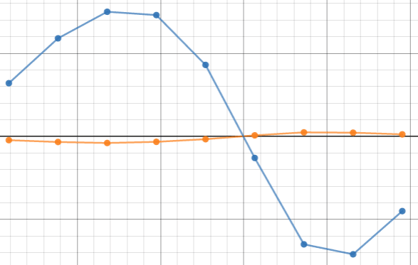
After steering initiation, where Fy first appears, we have the below graph showing change in Accel_x(organge) and Ay(blue) in 10 seconds, given some initial turn Velocity(along x-axis)... so to clarify we are looking at the change in Ax and Ay after steering is complete and a constant steer angle is held, in ACCEL:

Screen_shot_2021-01-13_at_2.41.36_PM_a2dvva.png


Ay can be about 20x Ax given some initial velocity.. Something fairly interesting comes up here: there exists some V such that the change in Ax and Ay (after steering) is 0, meaning throughout the turn there will be NO change in either Fx or Fy.. (at about 30mph (14m/s) in the graph shown where Ax Ay cross)
 
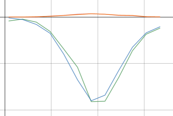
Adding to this: shown below are the corresponding plots for fixed accel through steer only(ie stop accel after steer) in blue, and fixed accel until steer(ie stop accel before steer) in green... Ax in both cases is near identical, in orange.

Screen_shot_2021-01-14_at_7.54.16_AM_wgnlyj.png


As we would assume, the closer to mu*g we get the less Ay is going to change during the turn since it will be maxed out(at the far right)

I feel these change in Ax and Ay plots have some relevance since very little is available studying transients like these, albeit this study is only conducted on a fully rigid model and in simulation, I hope it will shed some light on what happens in lateral(for my studies)

EDIT: (after more analysis) one take away from these plots is that there is a certain entry velocity where its better to accelerate through the turn vs not... I see that no accel in turn helps distribute Fy more evenly between inside and outside tires (which is a big help not "overloading" the outside tire at max friction), however the reduction in Fy reduces velocity, bad thing.. so to recap:

Fixed ACCEL better than no accel in turn at some velocity
 
GESpo said:
If I tested pushing a stationary vehicle to gain insight on F_y, how much different(mathematically) would that be than to push an already rolling tire?

F_y as your calling it will vary wildly in the real world depending on a lot of factors ranging from wheel bearing design and stiffness to tire pressure.

Remember that as the tire rolls, the tire is deflecting continuously at the contact patch and the bearings throughout the system are creating a drag moment that increases with speed.

In short, F_y will increase at some rate relative to wheel speed; in order to calculate that rate you'll need to make a lot of intelligent assumptions/WAGs

There's also the factor that in the real world (your goal here seems to be a mathematical model, not a real-world design, so this may not really apply) the coefficient of friction between the tire and surface is going to vary very widely, and as a result the slip angle is also going to vary widely. A real trophy truck hauling ass off road in sand may have huge slip angles some of the time (traveling over firm surfaces with low coefficients of friction) and very small slip angles some of the time (traveling over very very soft surfaces where steering is provided by the front wheels acting as rudders).
 
For clarity sake, the above plots use a fixed deg per second steering, so the turn radius is changing as Vx increases. I’ll also add some plots for a fixed radius turn that will more closely correspond to the widely used traction circle, for comparison..
 
Since a fixed radius turn would require steering to be applied differently for ea Vx, we look at slips for fixed steering of 10deg in 1 sec.. as expected the slips are higher for accel through steer(blue) vs stop accel at steer(red). At some Vx its better to stop accel at steer..

Turn deg(ie lower means more slips) on X, Vx on y

Screen_shot_2021-01-21_at_8.49.51_AM_bzcwvh.png
 
Status
Not open for further replies.

Part and Inventory Search

Sponsor