Eng-Tips is the largest engineering community on the Internet

Intelligent Work Forums for Engineering Professionals

Off-road Long Travel Suspension 1

Status
Not open for further replies.

GEspo

Automotive
Aug 25, 2020
90
0
0
US
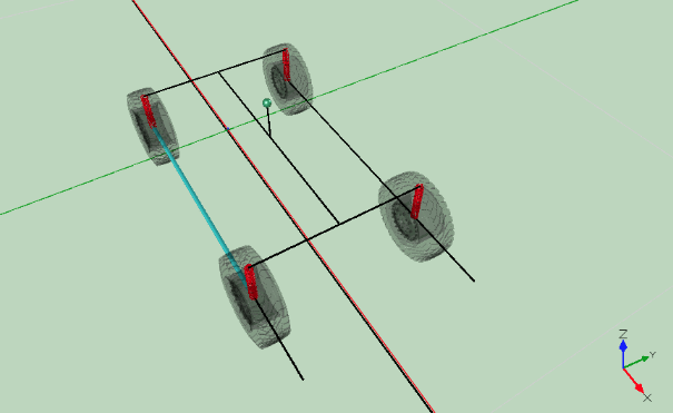
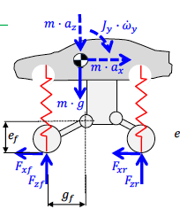
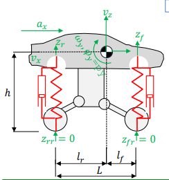
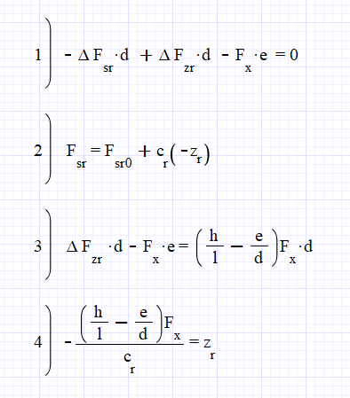
Hello eng-tips experts. For starters: I have a complete, fairly high fidelity, RBD simulation model of an off-road race vehicle, in Maplesim. Currently the model sits with IFS and a rear 4-link, triple bypass and dual rate coilovers on ea corner, real Modelon fluid flows. After a month or so working with the completed model, it's apparent the usual(pavement) race car dynamics analysis will only go so far due to the low coefficient of friction, ie dirt and tire, looks to be about .6, so lateral g's are restricted, and lots of sliding happens, just watch any race etc... SO to my question: Turning my focus to BUMP characteristics and analysis, are there any good resources that layout the study of long travel suspensions? Seems like studying a slinky would be more helpful than opening a dynamics book(I've opened a few btw)..

(As a guide, I'll generalize and define "long travel suspension" as a VERY Soft system with anywhere from 20" to 30" of travel..)
 
Replies continue below

Recommended for you

The different "interpretations" are at least in part due to differing simplifying assumptions being made.

The entire concept of "geometric/kinematic roll center" is a simplifying assumption.

A simplifying assumption inherently means that it will be at least a little bit wrong.

But NOT making the simplifying assumption may lead to a situation that cannot practically be analysed using the tools at hand.

When you start getting linkage pivot axes that are non-parallel with the vehicle's primary co-ordinate axes in both side view and plan view ... good luck analysing that in 2D or with pencil and paper. It is not happening. And lots of modern suspension designs are like that.
 
RCH does tell you something directly useful - how much of your roll gain is going to be needed to be supplied by your a/r bars.

Or if you are not directly concerned by roll gain, how much roll steer you'll be getting per g of cornering.

In the early stages of a car design, when we are still in spreadsheet world, rch is useful, it lets me define a target, even if I can't work out the rch of the intended suspension by hand, I can assume that down the track I'll get it right. In practice these days we get into ADAMS so quickly that the spreadsheet phase is almost redundant. Slightly O/T the last time I remember spending more than a week in spreadsheet mode was when we were designing a 4 bar link live axle. CAD had given me the likely areas we could put each bushing for the 2 arms, and development had come up with a roll steer target, and I had set a pinion nose pitch angle gain target (otherwise the the rear UJ causes problems).

A bit of 2d geometry and I had a parametric model in excel, then I just montecarloed it until we had a solution. As you can see articulation wasn't a particular target for this version

everest_rear_susp_hyjhjw.jpg


Cheers

Greg Locock


New here? Try reading these, they might help FAQ731-376
 
Hate to admit these wiki articles actually helped


Weight transfer may end up being a consideration with such large suspension travel. On the 4bar link live axle: my model is using custom contact joints for the rear 4-link lower links at frame.. I discovered quickly their huge influence on the system. The typical race truck is ifs front and 4-link rear(with parallel lowers, stiff bushings) so there is little rear axle lateral rotation. Issues I see right away in cornering is front wants to flex laterally(ifs) and rear has no lateral flex so we get lifting inside tire.. one motivating factor for locating any rotation points(roll center, pitch center).
 
After reading around a bit, getting armed for this investigation/analysis on roll center, looks like load transfer is of much greater significance than weight transfer; load transfer includes weight transfer but not necessarily. If I have this correct, for front ifs(or even no suspension idealized), load transfer is occurring(path) from the CP to the com_t(com of total vehicle), so the picture I'm getting, long or lat, is a triangle formed by ea CP(bottom vertices) to the com_t(top vertex), with a moment from the com_t acting on the CP(one side etc), moment arm would be com_t height(splits the "triangle" in half, from ground).

As far as lat forces on ea CP, you can calculate 2 ways?

1) get ea (dynamic/transferred) tire load(from formula) and multiply by centripetal accel?(possible ?)
(makes simplifying assumptions)
outside tire has 3x lat force than inside?? (for race car on track in eg)

2) using cornering stiffness and slip angle

Thoughts?
 
Gotcha.. I’ll keep posting as I increase my understanding of the system. One goal that should be attainable shortly is being able to compute forces on the suspension links at an exact point.. which I can use for my FEA on various suspension components. Will come in very handy even if it’s a close approximation..

Curious.. how much Lagrangian mechanics vs Newton is seen in the professional setting? Just situational which to use?
 
Screen_shot_2020-12-08_at_8.07.49_AM_j5a5cb.png


Calculating pitch forces required some understanding on the anti's, so attached here is a good pic of whats going on IN steady state ACCEL... this is after static equilib etc. The force generated at the rear CP(when toque applied to wheel) in PURPLE has change in Fz,r as the vertical component and is needed for finding out how much the rear spring will compress or unload FROM equilib, ie how much force is acting on the body(via moment at the vpp) to either unload the suspension(upward) or in the case of squatting, acting downward (from the anti squat line toward the vpp) but still will counter the load transfer and weight transfer(internal), ie the transfer(in to the spring) that would occur w/ NO suspension links..
 
Eventually there will be a question when I try to relate lateral aspects..

(Also, should this post turn into a good resource discussing the more complex aspects of designing a long travel suspension for a high speed application?)
 
The following is being added to help analyze the solid rear axle and ifs front. Shown below are 2 trivial suspensions used in simulation. They differ by how the wheels are connected, ie rear wheels rigidly connected(t1) vs right wheels rigidly connect(t2, not possible but helpful for lateral analysis). Both are without linkage connecting "body" to wheels, ie springs are the connections between body and wheels/axles. In lateral simulation I noticed a large difference in sprung mass transfer(smt), which I'll define(pls correct me if I'm wrong) as: change in vertical forces acting on the upper spring mounts. Load transfer at the CP is the same for both.

Trivial 1 (t1)
Screen_shot_2020-12-10_at_12.54.53_PM_xsybd5.png


and

Trivial 2 (t2)
Screen_shot_2020-12-10_at_12.55.22_PM_uaz9b8.png


Case 1 (long):
Given some torque to the rear wheels, acceleration, for longitudinal simulation, t1 experience smt as expected (rear loads, front unloads), t2 doesn't.


Case 2 (lat):
Given some torque to the rear wheels, acceleration AND turning, for lateral simulation, t1 experiences minimal but present smt, t2 large smt as expected(mainly load outside, unload inside but also present is a small difference in front and rear, rear loading a tiny bit more).

NOTE: all smt forces are easily accounted for by eliminating linkages in the trivial designs..


Relating the main topic of rear solid and front ifs, I'm thinking ifs will follow t2 and solid rear is t1, so we end up with.... (need more along with LOTS OF MATH)
 
I hope I didn't scare everyone away...

can someone explain what Jy is and how to measure it in the Jy * angular accel (acting on the com) in the below pic.. if J is inertia, then if using an inertia tensor the value is? Thanks!

Screen_shot_2020-12-11_at_4.17.24_PM_v7sike.png
 
Chalmers_pic_1_amnpid.png


Zr_formula_ol3ahu.png


From a few resources, one from the above post on antis, we solve for the displacement Z_r. C_r axle stiffness(can be spring rate for trivial designs), F_sr spring force. Eqn 1 is equilib at rear pivot(vpp or IC etc). Eqn 2 rear spring force w/ displacement. Eqn 3 from above on antis. Eqn 4 sub 2 3 into 1, solve. F_x= ma. d,e,h,l from above


So.. keeping things simple with trivial suspensions(or close to), for the model t2 above how do we get Z_r=0 using our formula? d=l e=..?
NOTE: the Z_r formula above seems to hold for trivial suspensions where d,e=0 like t1, as well as non trivial(I've only tested a few so I need to further verify)
 
More on t2 above

Let's see if I understand this correctly: Fx and ma are an action reaction pair, that can have suspension, ie coils and links connecting/between them in a non rigid connection, or can be rigidly connected, like a table with a book on it, or a train car(without suspension) carrying a load. Suppose a train car was carrying a mass suspended by springs, t2 above tells us that some Fx acting on the train car wheels will NOT interact with the sprung mass carried by the train car, so no sprung mass transfer.

Note Zr above uses Cr and Fx, however Fx must be able to act through the suspension on Cr to get a Zr... thoughts?
 
Status
Not open for further replies.
Back
Top