Hi Team,
Long time lurker, first time poster.
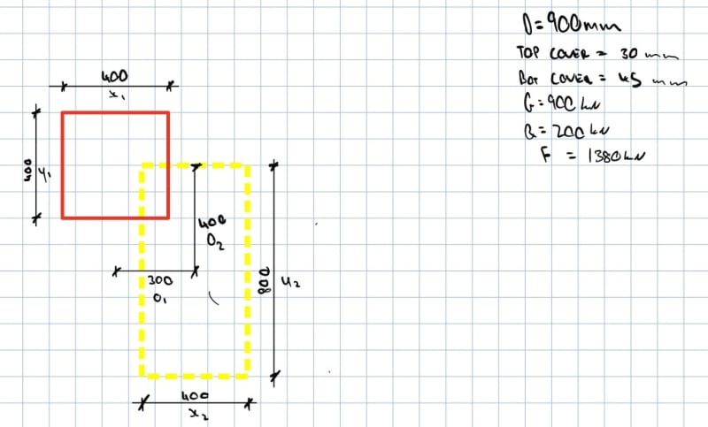
I know this is a pretty hot topic on these forums - though being relatively green and new to strut and tie modelling, I would appreciate some advice on developing a strut and tie model for a column transfer in line with the below preliminary sketches.
My questions are in line with the below:
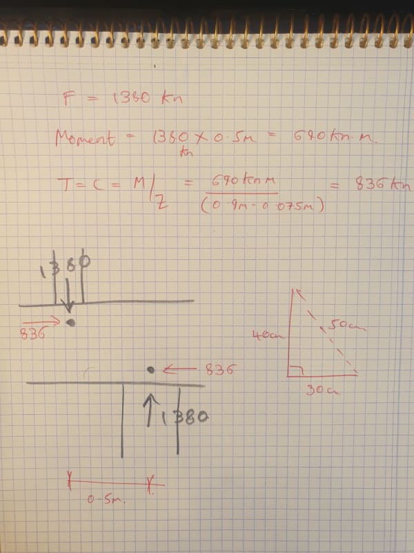
1. How do you define the height of the bottom node? Tough to find guidance on this in the standards I have looked at. The example above is just using the area below mid-depth of the slab as it is likely already in compression.
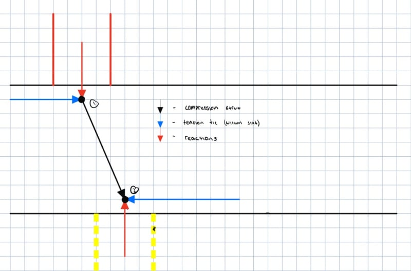
2. Will both nodes 1 and 2 act as CCT nodes in line with the below? I am pondering whether at node 2 in particular, the continuous slab surrounding the node can act as a restraint (surrounding concrete being in compression), and in turn make node 2 a CCC node.
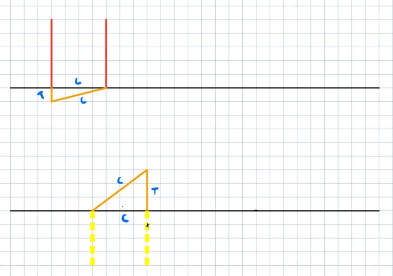
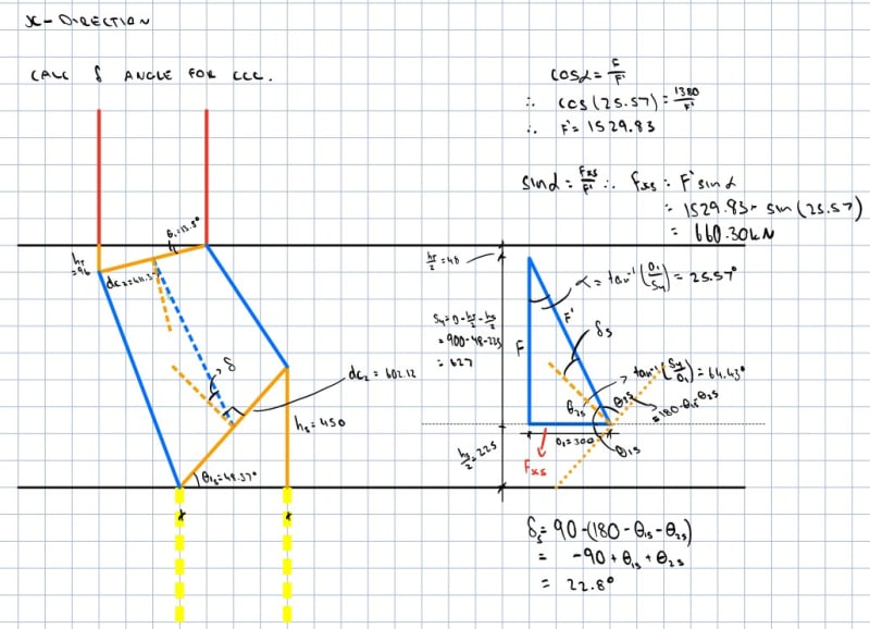
3. If the cardinal directions are checked and justified with this same model, is placing the reinforcement in these cardinal directions (rather than connecting the plan centroids of each column) justified?
Any help/thoughts would be greatly appreciated!
Thanks very much.
Long time lurker, first time poster.
I know this is a pretty hot topic on these forums - though being relatively green and new to strut and tie modelling, I would appreciate some advice on developing a strut and tie model for a column transfer in line with the below preliminary sketches.
My questions are in line with the below:
1. How do you define the height of the bottom node? Tough to find guidance on this in the standards I have looked at. The example above is just using the area below mid-depth of the slab as it is likely already in compression.
2. Will both nodes 1 and 2 act as CCT nodes in line with the below? I am pondering whether at node 2 in particular, the continuous slab surrounding the node can act as a restraint (surrounding concrete being in compression), and in turn make node 2 a CCC node.
3. If the cardinal directions are checked and justified with this same model, is placing the reinforcement in these cardinal directions (rather than connecting the plan centroids of each column) justified?
Any help/thoughts would be greatly appreciated!
Thanks very much.