Continue to Site

Eng-Tips is the largest engineering community on the Internet

Intelligent Work Forums for Engineering Professionals

  • Congratulations SDETERS on being selected by the Eng-Tips community for having the most helpful posts in the forums last week. Way to Go!

offset truss bearing & compatibility torsion

Status
Not open for further replies.

struct_eeyore

Structural
Feb 21, 2017
264
First of all, happy memorial day to all of the workaholics and those obsessed enough with engineering to be on this forum today.

I've got yet another torsional compatibility question...

I'm removing a bearing wall, and instead using an an upset LVL with buckets for the existing trusses. I'm curious to what extent you would go to account for torsion in such a scenario. I've ran the withdrawal loads on the nails in the bucket - they work on their own, and this leaves me to think that I can take the shear all the way to the face of the LVL. The LVL sits on post on one end and on a HD bucket on the other. Assuming I clip the top of the lvl to ea. truss, would creating this nominal moment connection be sufficient to remove any unwanted tosion at ea. end of the LVL?


[URL unfurl="true"]https://res.cloudinary.com/engineering-com/image/upload/v1716836114/tips/TRUSS_OFFSET_hq6oft.pdf[/url]
 
Replies continue below

Recommended for you

If it is a 2-ply LVL, I don't look at torsion in these situations. I do attach to the trusses as you stated to brace the top flange though.
I was at the beach while you were working yesterday :)
 
XR - thanks for the response, although you're not making me feel better about the whole beach thing :(
In my case, it's a single ply, 3-1/2" wide LVL, supported on the simpson CCQ heavy duty caps.
 
The load depicted is eccentric, but compatibility torsion is a misnomer. Torsion would need to be resisted by torsional stress in the beam and torsional resistance at the beam supports.

When the members causing torsion prevent rotation of the beam, that is compatibility torsion. Your truss does not prevent rotation of the beam.
 
The torsion in this situation (3 1/2" wide LVL) is routinely ignored in residential (and commercial) wood construction without issue.
If you tried to resolve it, it would likely be the last job you got from that customer.
 
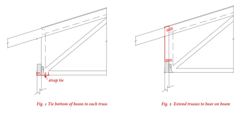
If you're really worried, sister a 2x12 (or whatever it needs to be) onto the truss at some interval (4 or 6 feet?), sport it with a double hanger, and use a dtt1 tension tie to retain the top of the beam.

I've done this for large eccentric for loads on a wood beam when taking out the bearing wall below. Though I've only done it to sawn lumber joists.
 
XR250 said:
If you tried to resolve it, it would likely be the last job you got from that customer.

I doubt that, but it shouldn't matter even if true. Following are a couple of ideas.

Capture_a0ampw.jpg
 
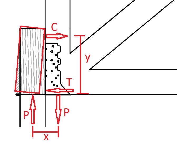
If the truss end has a vertical reaction P which acts somewhere on the metal connector seat, then the way I see it, there will be a torsional moment, TM = Px per my sketch. This will cause the bottom of the beam to want to rotate away from the bottom of the truss (which I drew as the beam in red). The tension, T, and compression, C, forces will counteract this torsional moment. (I screwed up the direction of the C and T arrows, I just realized. They should be reversed.)

beam_with_torsion_zo0jup.jpg


I would expect the C force to be near the top of the beam and the T force near the bottom, separated by distance, y, per the sketch. This makes it possible to solve for T and C. Possibly the T force can be resisted through the connector, or more likely, some direct tension connection maybe like a metal strap down the face of the beam, along the bottom, and along the bottom of the truss. The C force is resisted by direct bearing against the truss. I would also provide some sort of clip there in case somehow the beam were to experience lateral torsional buckling with the top trying to pull away from the truss, or if the truss has an uplift force.

Can the torsion on the beam be ignored? Yeah, perhaps.

Does connecting the beam to the truss in a way which resists torsion force the beam end condition to deviate from the pinned assumption? I think that's possible. And if the beam deflects and the end rotates, does that still cause the beam to rotate in torsion a little? I think so.

I might try to use a top mount connector here instead.

EDIT: BA_Retired beat me with a few good ideas, I just noticed. The detail with the strap is exactly what I was thinking.
 
Right. Forget my idea unless there's uplift. I got that flipped around. Thanks for the image, Eng16080. I'm with BA's figure 1.
 
When I get to a 3-ply LVL (5 1/4"), I add straps on the bottom of the trusses/joists that go under the beam and wrap up the exposed face to resolve the tension portion of the couple. Can also use a DTT1Z as I think Pham mentioned.
 
Status
Not open for further replies.

Part and Inventory Search

Sponsor