Continue to Site

Eng-Tips is the largest engineering community on the Internet

Intelligent Work Forums for Engineering Professionals

  • Congratulations GregLocock on being selected by the Eng-Tips community for having the most helpful posts in the forums last week. Way to Go!

Old Railroad Bridge for Bikepath Bridge 3

Status
Not open for further replies.

3Fan

Structural
Dec 21, 2005
78
We are working on a cost proposal for an existing 800' long (mulit-span) railroad bridge from the early 1900's that is to be converted into bike path bridge. The bridge was used until the mid 90's and is in really good condition. There are 2 built-up plate girders that are spaced at the gauge of the rail (4'-8.5"). The owner wants a Ipe wood deck that is 14' toe/toe of railing and to support an H10 loading. The piers are not wide enough to add additional beams beside the girders. Just wondering if anyone has run into a project like this before and what you came up with for a deck system. Our thought was to place W sections perpendicular to the girders and then run stringers on top of them with the Ipe deck on top of the stingers. Problem is the cantilever of the perpendicular beams will more than likely be greater than 5.5' and result in a large section and increased costs.

Any thoughts?
 
Replies continue below

Recommended for you

I would consider a modified girder-floorbeam-stringer arrangement, where instead of a floorbeam between the girders, it would have brackets/corbels on the exterior side of the girders, similar to the overhang brackets used to support cantilevers during construction, but obviously much heftier. If it doesn't have stiffeners on the exterior side of the girders at the diaphragm locations, you'd have to add them for connection plates. They'd need to align with the diaphragms or cross-frames between the girders, so the spans of the stringers will be equal to the existing diaphragm spacing.

Rod Smith, P.E., The artist formerly known as HotRod10
 
H10 truck is still an 8 kip concentrated load.

Here's another thought... Forego all the secondary steel framing and go with precast deck panels. I'm calculating out that you will have a 4.6ft cantilever either side. A 6" thick concrete deck should be sufficient. Fasten longitudinally oriented recycled plastic lumber nailers to the top of the deck and then nail your IPE into that. This will also make your railing post connection detail quite a bit more straightforward. Your biggest concerns with this would be...

1. Weight. Ensure new Strength 1 load does not exceed old load on foundations.
2. Whether or not you want to pour a closure pour at each of the transverse joints.
3. Do you envision them lifting panels into place with a crane or rolling them out on dollies and picking them with an excavator/forklift.
4. How to make the connection between the panel and the top flange of the girder. This may be the most expensive field portion of the work. This is typically still going to need a CIP haunch.
5. Will you want to have some drain hole blockouts every so often to mitigate ponding water?

I offer this perspective from an area of the country where we do more concrete work than steel work so it might not make sense in your part of the country. With the option you described, if you want to flush frame the transverse W sections perpendicular to the girders I foresee a lot of expensive in-field steel connection work.
 
3Fan said:
...railroad bridge...that is to be converted into bike path bridge.
The owner wants a Ipe wood deck that is 14' toe/toe of railing...
...to support an H10 loading.
Problem is... increased costs.

In the 1990s, I worked with a Rails-to-Trails group to establish cost effective design criteria for a similar project.

The general guidelines we settled on was a treated lumber deck, suitable for the 5' width of a John Deere Gator (for trail maintenance), and load rating to be determined based that vehicle.

Design was turned over to an engineering firm.

My point is that organizations of this type often don't have realistic understanding of what is technically & economically reasonable. Unless the requirements are fixed, suggest reviewing where those requirement came from and explaining that "there is no free lunch".

[idea]
 
Good point SRE. Is 14' a need or a wish? A clear width of 10' can likely be done at a cost that's half or less that of the 14' width, at least for the wood deck option. The difference might not be as dramatic for the precast panels, but the 14' option with a 5'+ cantilever, will require a positive connection between the panel and the girder (the panels will need to be anchored down to the girders to prevent tipping with the H-10 truck over to one side).

Rod Smith, P.E., The artist formerly known as HotRod10
 
10' is fine on a short bridge, but on such a long structure, the added width would be highly desirable so ambulances, maintenance trucks, etc. could pass trail users.

My glass has a v/c ratio of 0.5

Maybe the tyranny of Murphy is the penalty for hubris. -
 
Thanks for the ideas and concerns. My list of concerns is double or triple that you have listed above. We've stressed that the owners 14' clear width will be difficult to achieve. They are not wanting to budge on the width at this point. Our one saving grace may be that in one of the spans there is a truss (as opposed to plate girders) that span over another active railroad. The face to face width of truss will determine the trail width. No one has been able to gain access to that yet to put a tape on it, but guessing we are at least 12.5'.

SlideRuleEra, we made the suggestion to buy the local fire department a Gator to access this bridge in order to cut down on the width and cost. But the owner still desires 14' face/face of rail. Lots of great info on that Rails-To-Trails site. Thank you. And I echo your statement about "there is no free lunch."

BridgeSmith, yes there are plenty of stiffeners. I like that idea of adding on overhang brackets to support a line or two of stringers outside the existing plate girders. One common design for all the spans could be developed. How would you add stringers in between the existing plate girders as I doubt the Ipe will span 4'-8.5"

Forgot to mention that the bridge is on a curved alignment and all the plate girders are not the same depth in adjoining spans. I think they moved many different bridges from various locations to this location as I saw plaques with 1904 and 1912 on them.

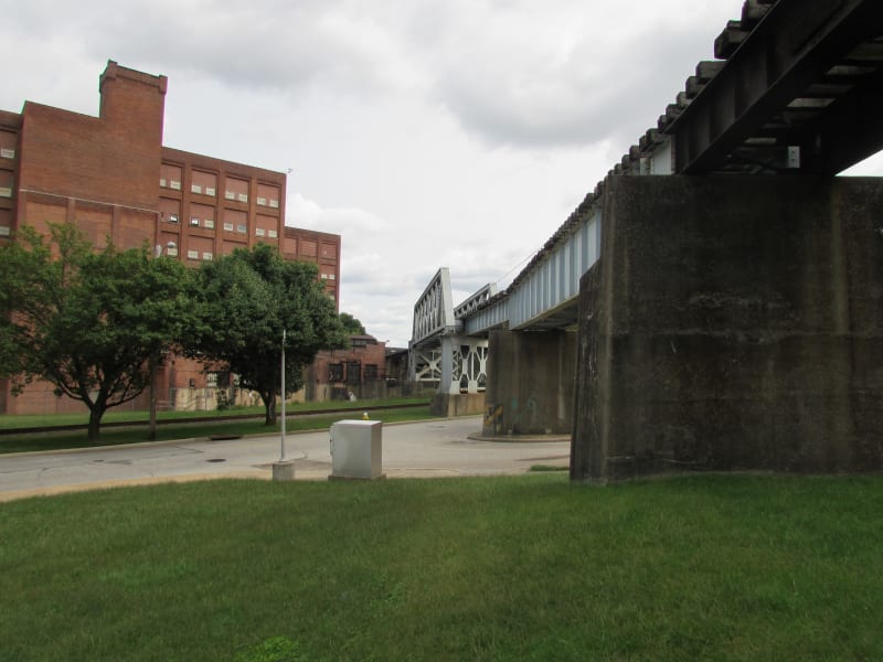
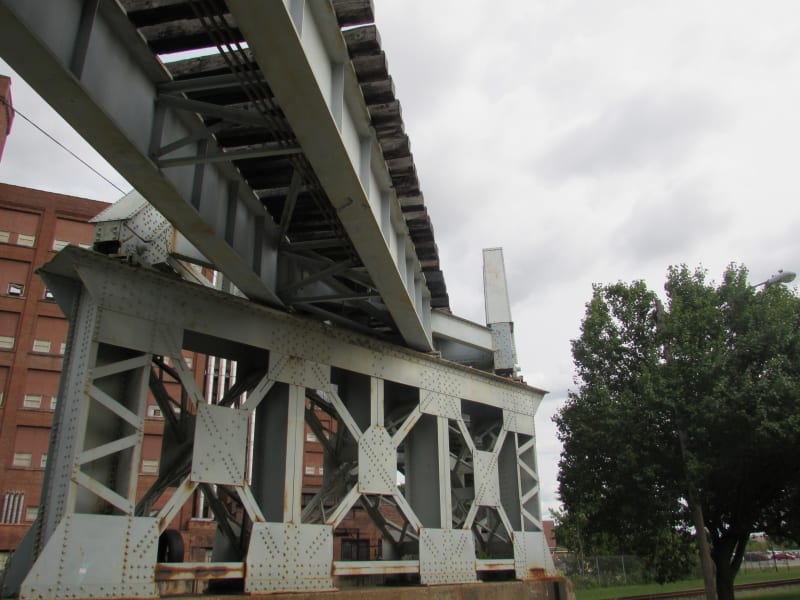
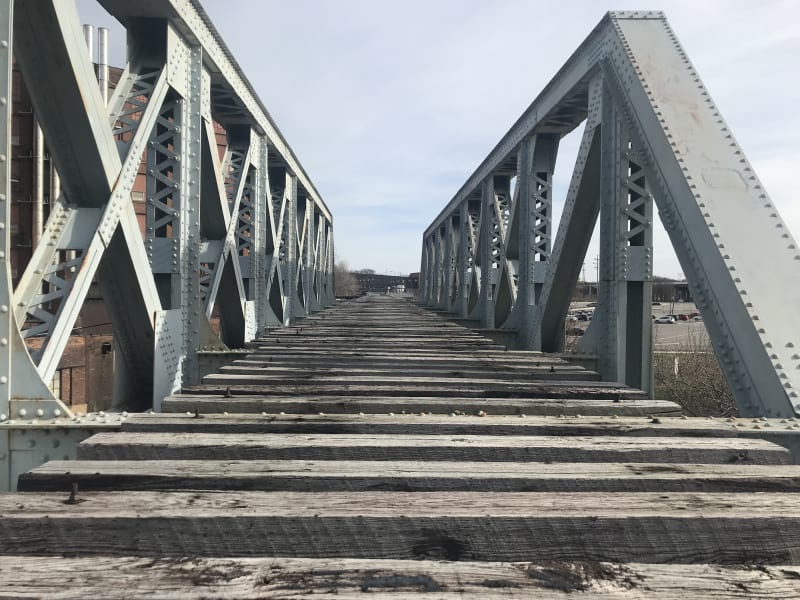
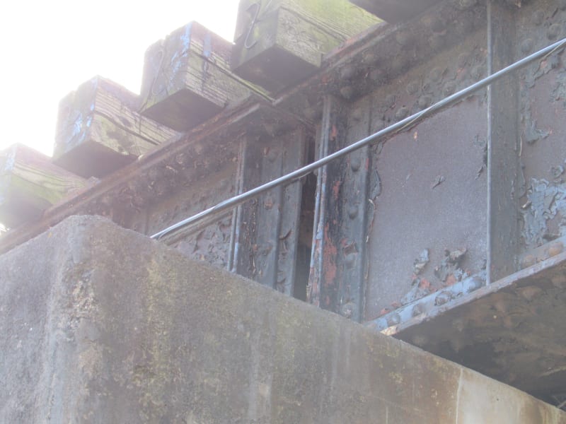
Here's a couple photos.

IMG_2111_c7moce.jpg


IMG_2104_ljnjwo.jpg
 
3Fan said:
The bridge was used until the mid 90's and is in really good condition.
...all the plate girders are not the same depth in adjoining spans.

That won't be a problem, H10 loading on a RR bridge in good condition is just "noise". By 1900, RR bridges were commonly designed for Cooper E40 (40K per locomotive driving axle, followed by rail cars at 4K / ft of track... and that is for steam locomotives which pound the rails).

If the bridge had been upgraded, at least Cooper E72 (Cooper E40 x 1.8) by the 1990's.

Nice photos, what (approximate) location?

Edit: If the client want's to save a lot of money, see if you can convince them to just put decking on the cross ties (each cross tie likely about 8.5' to 9' long). We convinced the organization that I worked with to do this on the 4 or 5 timber RR trestles that lead up to the wider 1900 steel swing span.

[idea]
 
Totally agree that the H10 won't be noticed by the existing structure. We are not to analyze the existing structure.

Not sure the condition of the cross ties and the owner stated he wanted them removed. Good thought though, if owner wanted a 9' wide deck. Another local rails to trails project just laid ties right beside each other and paved over them. Those girders were spaced wider than these and only resulted in 2' overhangs.

Project is in Northeast Ohio.
 
BridgeSmith, yes there are plenty of stiffeners. I like that idea of adding on overhang brackets to support a line or two of stringers outside the existing plate girders. One common design for all the spans could be developed. How would you add stringers in between the existing plate girders as I doubt the Ipe will span 4'-8.5"

To alleviate concerns about torsional rotation of the girders, you'd want to put the bracket for the external stringers at the locations where the crossframes are between the girders.

Whether the wood will span between the girders is a matter of its thickness and whether the planks are securely connected together, so the wheel load gets distributed across multiple boards. Incorporating a stringer between the girders will likely require modification or replacement of the existing crossframes. As SRE wrote, if the existing ties are in good shape, they could be left in place to support the decking.

You could incorporate corrugated steel decking running transverse, and then run the wood decking longitudinal.

Rod Smith, P.E., The artist formerly known as HotRod10
 
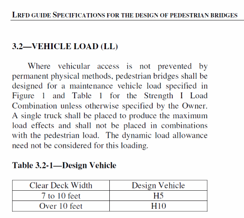
Understood, I promise not to be a "pest", (and you may know this) but here is one more possible "sales" tactic to put in your pocket if the Owner balks at the price of 14' wide, H10 structure:

An AASHTO 7' to 10' wide, H5 structure "AASHTO LRFD Guide Specifications for the Design of Pedestrian Bridges"

Loading-500_chfjhi.png


I don't have the standard but do have the (public) original vesion final draft, see attachment.


[idea]
 
Most bike path bridges need only 10’ clear distance, not sure what the 14’ is all about.
 
The path off the bridge is 10' paved with 2' shoulders. The owner is stuck on that 14' width across the bridge also. We have expressed to them that the construction cost escalates exponentially over a 10' deck. But we are back to 14'.

Running decking longitudinally is frowned upon amongst the biking community.

IPE decking is expensive and bigger stuff is not easy to come by.

Great ideas folks.
 
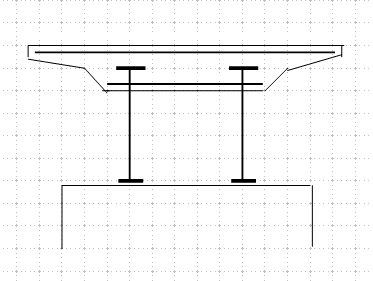
Just a suggestion. You can add more weight to the middle concrete block to offset the cantilever effect.

image_ic1cmk.png
 
Given the expense of the Ipe (and not being able to have it run longitudinal), the more economical choice may be to have a separate structural deck system using concrete, steel grid, concrete filled corrugated steel decking, etc., and adding the Ipe as a thin non-structural flooring.

Rod Smith, P.E., The artist formerly known as HotRod10
 
I know it won't give you quite the cantilever you're looking for by itself, but what about replacing the Ipe decking and stringers with treated glulam bridge deck panels? The US Department of Forestry has a bunch of typical details for rural bridges that use it. A large bridge in Canada used CLT panels, but they also had to cover it with marine ply and membrane to protect the wood (CLT doesn't come with preservative treatment).
 
Just an update on this project. I was able to visit the site and get up on top of the bridge. The truss inside to inside width will be our controlling width of about 12'. The girder spacings vary from 6.0' to 6.5' to 8'. So the overhangs will vary. One snag we noticed at the site was that the girders are all built up sections with plate and angles and constructed with rivet. The rivets are stitched at about 4" centers in the flanges. The heads protrude up maybe 3/4" making placing anything flat on the existing flange very difficult to do. We have tried to convince the owner to use CIP concrete but he's not liking that idea. He's still stuck on using wood only or a steel and wood combination. Not sure how we would attempt to mount steel to the top of the flanges with the rivet heads sticking up. The existing wood ties that were still in place were notched to go over the heads.
IMG_0482_h7lsbl.jpg
IMG_2372_mvnggk.jpg
 
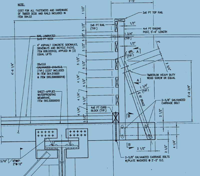
Here's a detail we used. A C-channel was welded on the girder to provide a smooth surface for the nail-laminated wood deck. C-shaped plates around the girder flanges provide uplift restraint. They are nailed in between the deck boards. The wearing surface is two lifts of HMA on a waterproof membrane.

Albany County Rail-Trail - Normans Kill Bridge

path_deck_detail_nnetxs.png


My glass has a v/c ratio of 0.5

Maybe the tyranny of Murphy is the penalty for hubris. -
 
Status
Not open for further replies.

Part and Inventory Search

Sponsor